A mems microstructure three-axis excitation device driven by piezoelectric ceramics

A piezoelectric ceramic drive and excitation device technology, which is used in measurement devices, machine/structural component testing, vibration testing, etc. The effect of force data, smooth adjustment process and accurate measurement values

Active Publication Date: 2019-05-31
广林特装车(锦州)有限公司
View PDF13 Cites 0 Cited by
  • Summary
  • Abstract
  • Description
  • Claims
  • Application Information

AI Technical Summary

Problems solved by technology

[0006] 2. There is no direct connection between the upper connection block and the lower connection block and the sleeve, but are installed in the sleeve in turn by means of clearance fit. If the parallelism error of the two working surfaces of the stacked piezoelectric ceramics is large , there is not enough space to adjust the movable base structure;
[0007] 3. The pressure sensor is installed at the bottom of the lower connecting block. Since the movable base structure adjusts itself, there is a certain inclination between the bottom of the lower connecting block and the working surface of the piezoelectric ceramic, so the pre-tightening force measured by the pressure sensor Or the output force of piezoelectric ceramics is not accurate; in addition, if the movable base structure causes the upper coupling block or the lower coupling block to contact the sleeve after adjustment, the error of the measurement result will further increase;
[0009] 5. In this device, gaskets of different thicknesses are used to change the magnitude of the pre-tightening force applied to the stacked piezoelectric ceramics, which makes the adjustment process complicated and not flexible enough

Method used


Image

  • A mems microstructure three-axis excitation device driven by piezoelectric ceramics
  • A mems microstructure three-axis excitation device driven by piezoelectric ceramics
  • A mems microstructure three-axis excitation device driven by piezoelectric ceramics

Examples


Embodiment Construction

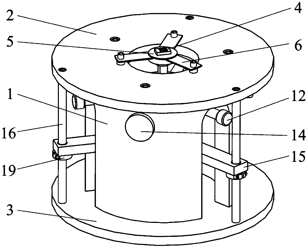
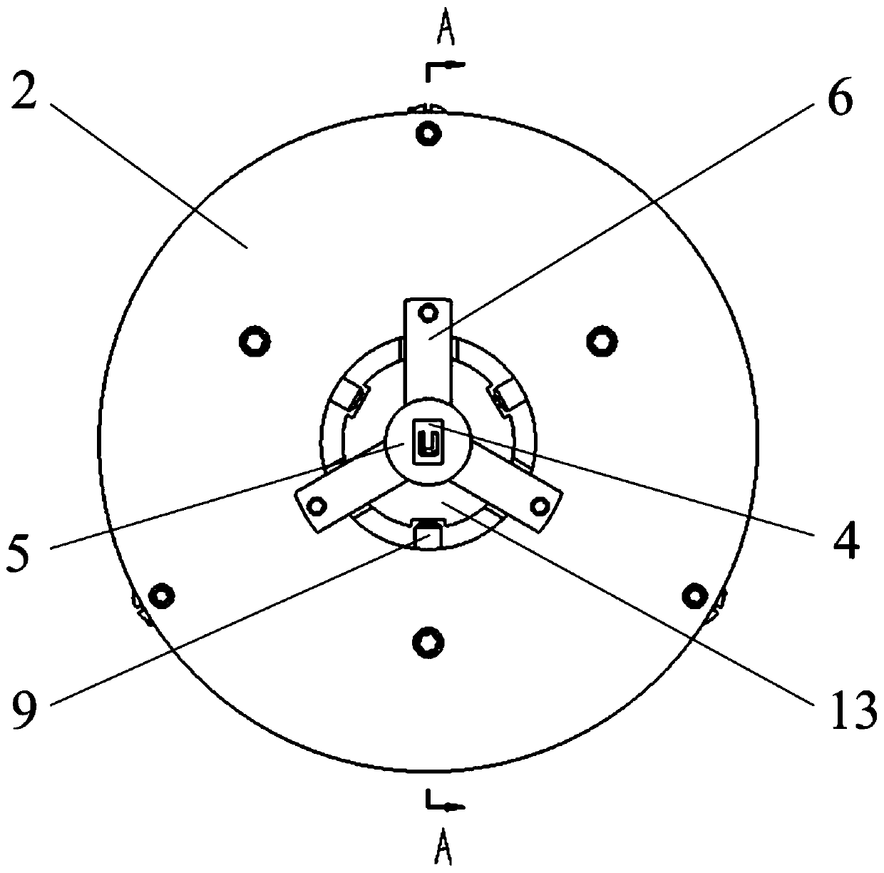
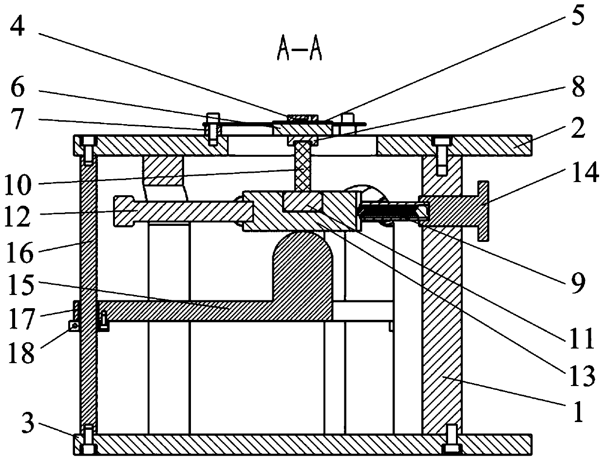
[0038] Such as Figure 1 to Figure 7 As shown, the present invention relates to a MEMS microstructure three-axis excitation device driven by piezoelectric ceramics, comprising a hollow sleeve 1, in which a stacked piezoelectric ceramic 10, a pressure sensor 11 and a The movable base formed by the upper coupling block 13 and the lower coupling block 15 is provided with an elastic support 6 and a MEMS microstructure 4 on the sleeve 1 .

[0039] An annular top plate 2 and a bottom plate 3 are respectively fixed on the upper surface and the bottom surface of the sleeve 1 by screws, and the MEMS microstructure 4 is mounted on the annular top plate 2 through an elastic support 6 . Described elastic support member 6 is made of a cylindrical pressing piece 601 and three supporting pieces 602 that the circumference is evenly distributed on pressing piece 601 outer edge, and the thickness of described supporting piece 602 is less than the thickness of pressing piece 601; The amount of ...


PUM


Abstract

The invention discloses an MEMS micro-structure three-axis type excitation device driven by piezoelectric ceramics. The MEMS micro-structure three-axis excitation device comprises a sleeve, a stackedpiezoelectric ceramic, a pressure sensor, an upper connecting block, a lower connecting block and an MEMS micro structure; an annular top plate is arranged at the upper end of the sleeve, the MEMS micro-structure is installed on the annular top plate through the elastic supporting part.; the upper end of the lower connecting block is a hemispheric round head and abuts against the bottom surface ofthe upper connecting block; the piezoelectric ceramic is clamped between the pressure sensor and the elastic supporting piece; ball head plungers are uniformly distributed between the upper connecting block and the sleeve, and the inner ends of the ball head plungers are jacked into a sliding groove in the outer edge of the upper connecting block, and guide shafts are uniformly distributed between the annular top plate and the bottom plate. According to the device, pre-tightening force of different sizes can be applied to the stacked piezoelectric ceramics, the obtained pre-tightening force measurement value is more accurate, so that the adjustment process of the parallelism error of the two working surfaces of the stacked piezoelectric ceramic can be smoother, the shearing force of the layers of the stacked piezoelectric ceramics is reduced, and the dynamic characteristic parameters of the MEMS micro-structure can be tested conveniently.

Description

technical field [0001] The invention belongs to the technical field of micromechanical electronic systems, in particular to a MEMS microstructure three-axis excitation device driven by piezoelectric ceramics. Background technique [0002] Due to the advantages of low cost, small size and light weight, MEMS microdevices have broad application prospects in many fields such as automobile, aerospace, information communication, biochemistry, medical treatment, automatic control and national defense. For many MEMS devices, the micro-displacement and micro-deformation of their internal microstructures are the basis for the realization of device functions. Therefore, accurate testing of dynamic characteristic parameters such as the amplitude, natural frequency, and damping ratio of these microstructures has become the key to developing MEMS products. important content. [0003] In order to test the dynamic characteristic parameters of the microstructure, it is first necessary to ma...

Claims


Application Information

Patent Timeline
Patent Type & Authority Patents(China)
IPC IPC(8): G01M7/02G01H9/00
CPCG01H9/00G01M7/00
Inventor 佘东生赵玉峰杨祯山郭兆正刘继行孙小楠
Owner 广林特装车(锦州)有限公司
Why Eureka
Try Eureka