Gas channeling simulation system

A technology for simulating systems and gas channeling, applied in measuring devices, instruments, scientific instruments, etc., can solve the problems of test result deviation, complex device structure, cumbersome test operation, etc., and achieve the effect of ensuring normal operation and ensuring accuracy

Active Publication Date: 2018-06-15
CHINA NAT OFFSHORE OIL CORP +1
View PDF6 Cites 5 Cited by
  • Summary
  • Abstract
  • Description
  • Claims
  • Application Information

AI Technical Summary

Problems solved by technology

However, the current test device has the following disadvantages: the device structure is complex, the test operation is cumbersome, the actual situation cannot be effectively simulated, and the test results have large deviations.

Method used


Image

  • Gas channeling simulation system
  • Gas channeling simulation system
  • Gas channeling simulation system

Examples


Embodiment 1

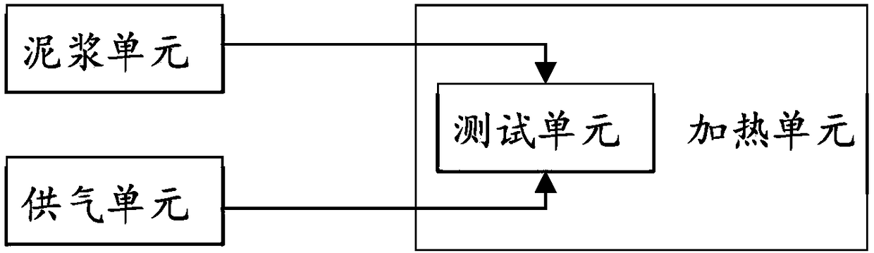
[0048] like figure 1 As shown, Embodiment 1 of the present invention provides a gas channeling simulation system, which may include a cement slurry unit, an air supply unit, a heating unit, and a test unit; wherein, the cement slurry unit communicates with the test unit, and the cement slurry unit is used to provide The cement used for testing; the air supply unit communicates with the test unit, and the air supply unit is used to provide a preset pressure for testing; the test unit is set in the heating unit, and the heating unit is used to provide a preset temperature for testing.

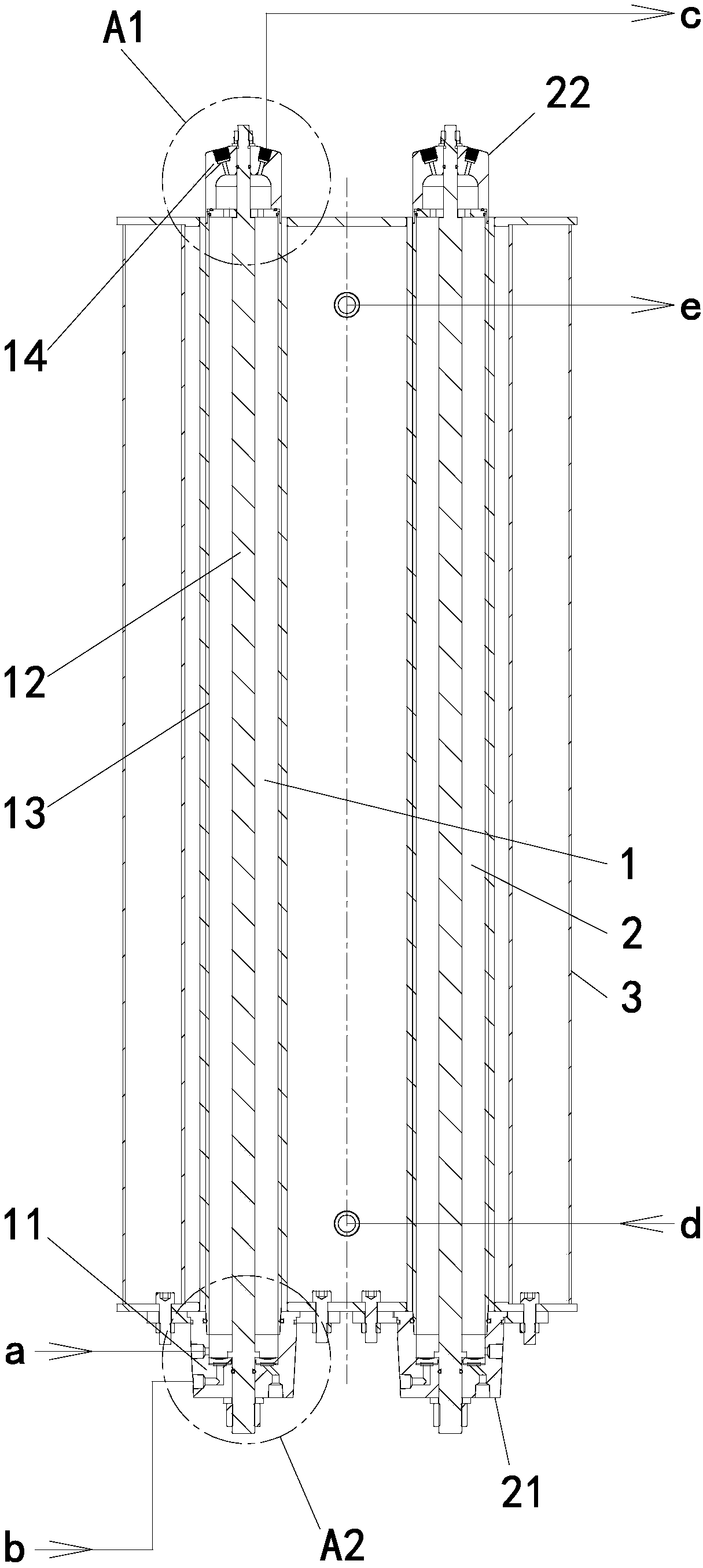
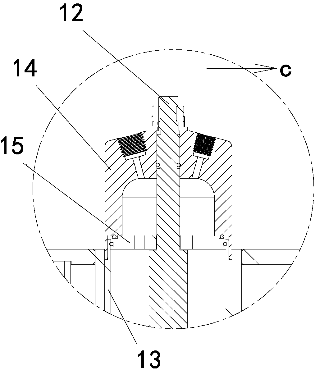
[0049] combine figure 2 , image 3 as well as Figure 4As shown, the test unit includes a heating cylinder 3, a gas channeling tube 1 for measuring the gas channeling process of cement, and a weight loss tube 2 for measuring the hydrostatic column pressure of cement; Inside the barrel 3, the gas channeling tube 1 and the weightlessness tube 2 are both provided with an annular cavity for conta...

Embodiment 2

[0078] Embodiment 2 of the present invention provides a simulation test method applied to the air channeling simulation system described in Embodiment 1, including:

[0079] Step a: Detect the hydrostatic column pressure value of cement per unit height in the weightless tube through the pressure detection mechanism, and calculate the hydrostatic column pressure value to be applied according to the detected value;

[0080] Step b: Perform pressurization operation through the pressure detection port of the gas channeling tube, apply the pressure value calculated above, measure the pressure at the bottom of the gas channeling tube and record the measured value;

[0081] Step c: When the pressure detection mechanism detects that the measured value of the gas channeling tube reaches a predetermined value, the gas with a constant pressure is introduced from the first gas input port;

[0082] Step d: Detect the amount of cement air channeling in the annular cavity through the pressur...


PUM


Abstract

The invention discloses a gas channeling simulation system, which includes a cement slurry unit, a gas supply unit, a heating unit and a test unit. The cement slurry unit communicates with the test unit and provides cement used for test; the gas supply unit communicates with the test unit and used for providing pre-set pressure used for tests; the test unit is arranged in the heating unit, which is used for providing preset temperature used for test; the test unit comprises a gas channeling pipe used for measuring the gas channeling process of cement and a weight loss pipe used for measuring the pressure of a cement hydrostatic column; the gas channeling pipe and the weight loss pipe are located in a heating cylinder and are provided with an annular chamber used for accommodating cement, and the bottom ends of the gas channeling pipe and the weight loss pipe are provided with pressure detection mechanisms, respectively; the bottom end of the annular chamber of the gas channeling pipe is provided with a first cement slurry input port and a first gas input port, and the top end of the gas channeling pipe is provided with a pressurization detection port; and the bottom end of the annular chamber of the weight loss pipe is provided with a second cement slurry input port.

Description

technical field [0001] This application relates to but is not limited to the technical field of oil well supporting equipment, especially a gas channeling simulation system. Background technique [0002] During the curing stage after cement injection, the upward channeling of high-pressure gas is the main problem in gas well cementing. [0003] The main reasons for gas channeling are as follows: 1. The cement sheath displacement efficiency is low during well cementing, forming a channeling channel entrained by cement slurry. If the pressure of the gas layer is greater than the pressure of the hydrostatic liquid column, the gas escapes along the channeling channel; 2. Due to Cement quality problems lead to poor bonding quality between cement and casing or formation cementing surface in the annular space, and gas leaks along the annular gap; 3. During the construction process, the total pressure of the cement slurry column and the cement slurry column is less than the pressure...

Claims


Application Information

Patent Timeline
Patent Type & Authority Applications(China)
IPC IPC(8): G01N33/38
CPCG01N33/383
Inventor 宋茂林罗宇维赵琥齐营刘海轩于斌
Owner CHINA NAT OFFSHORE OIL CORP
Why Eureka
Try Eureka