
Signal test device for network equipment

A technology for signal testing and network equipment, which is applied in the field of signal testing devices for network equipment, can solve problems such as inconvenient to carry work, not conforming to ergonomics, and not adopting wave-shaped design, so as to achieve easy viewing and recording, good use prospects, The effect of protective devices

Pending Publication Date: 2018-06-15
四川忠辉电子科技有限公司
View PDF0 Cites 0 Cited by
  • Summary
  • Abstract
  • Description
  • Claims
  • Application Information

AI Technical Summary

Problems solved by technology

[0002] Signal detection is mainly divided into three categories. One is in the field of electronic technology, the sensing, measurement and data acquisition of the original signal are mainly related to the hardware system; The process of extraction is mainly related to mathematical theory and software algorithm. The third is in the field of psychology, a systematic research and testing method for the problem of response deviation, which mainly focuses on the decision-making process of whether a stimulus event occurs or not; the existing signal test There are certain disadvantages in the use of the device. It does not adopt a wave-shaped design, does not conform to the ergonomics, the grip is not comfortable enough, does not have a certain anti-fall effect, cannot be tied with a lanyard, is not easy to carry and work, and is inconvenient to use the device. Placed on the desktop, it is not convenient to watch the record, and it has a certain impact in actual use. Therefore, we propose a signal test device for network equipment

Method used


Image

  • Signal test device for network equipment
  • Signal test device for network equipment
  • Signal test device for network equipment

Examples


Embodiment Construction

[0017] In order to make the technical means, creative features, goals and effects achieved by the present invention easy to understand, the present invention will be further described below in conjunction with specific embodiments.

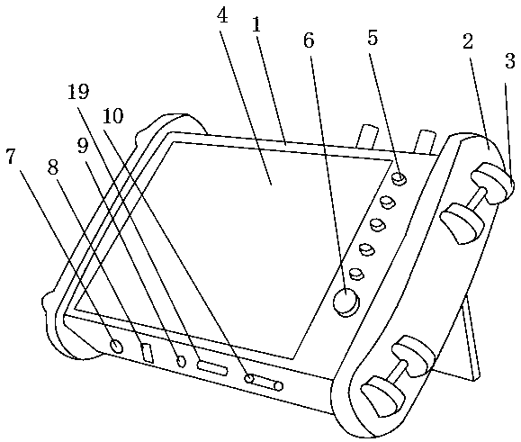
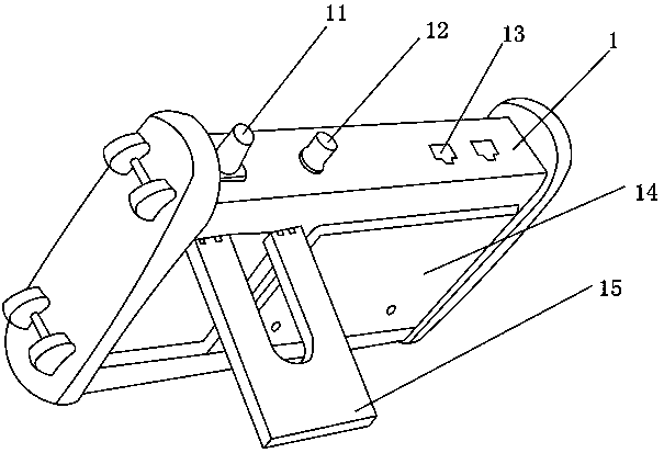
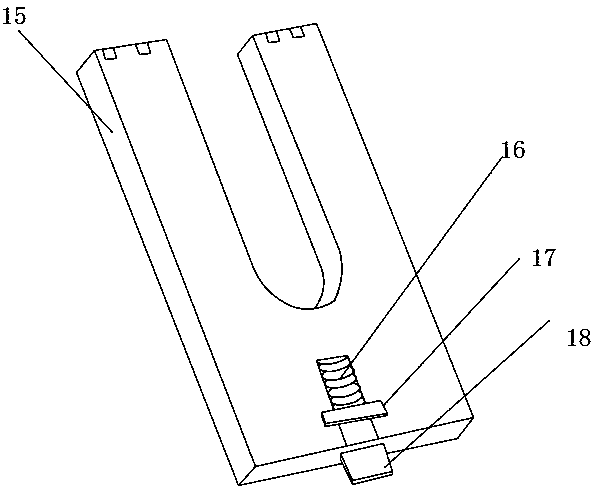
[0018] Such as Figure 1-3 As shown, a signal testing device for network equipment includes a device casing 1, a rubber handle cover 2 is provided on one side of the device casing 1, and a wire winder 3 is provided on the outer surface of the rubber handle cover 2, and the device The outer surface of the front end of the casing 1 is provided with a display 4, and one side of the display 4 near the outer surface of the front end of the device casing 1 is provided with an operation button 5, and a power switch 6 is arranged near the bottom of the operation button 5. The outer surface of the lower end is provided with a charging interface 7, and the side close to the charging interface 7 of the lower outer surface of the device casing 1 is provided w...


PUM


Abstract

The invention discloses a signal test device for network equipment. The signal test device comprises a device housing. The outer surface at one side of the device housing is provided with a rubber handle sleeve, and the outer surface of the rubber handle sleeve is provided with a winder. The outer surface of the front end of the device housing is provided with a displayer; one side, close to the displayer on the outer surface of the front end of the device housing, is provided with operation buttons; and a power switch is arranged under the operation buttons. The outer surface of the lower endof the device housing is provided with a charging interface, and one side, close to the charging interface in the outer surface of the lower end of the device housing, is provided with a USB interface. The signal test device for the network equipment is provided with the rubber handle sleeve, the winder and a support plate, adopts a wavy design, accords with ergonomics better, is more comfortableto grip, has a certain anti-break effect, can be tied by a hanging line to enable the device to be portable in work, and can be placed on a desktop conveniently, thereby helping to observe records and providing better use prospect.

Description

technical field [0001] The invention relates to the field of signal testing devices, in particular to a signal testing device for network equipment. Background technique [0002] Signal detection is mainly divided into three categories. One is in the field of electronic technology, the sensing, measurement and data acquisition of the original signal are mainly related to the hardware system; The process of extraction is mainly related to mathematical theory and software algorithm. The third is in the field of psychology, a systematic research and testing method for the problem of response deviation, which mainly focuses on the decision-making process of whether a stimulus event occurs or not; the existing signal test There are certain disadvantages in the use of the device. It does not adopt the wave-shaped design, does not conform to the ergonomics, the grip is not comfortable enough, does not have a certain anti-drop effect, cannot be tied with a lanyard, is not easy to ca...

Claims


Application Information

Patent Timeline
Patent Type & Authority Applications(China)
IPC IPC(8): H04B17/00H04B10/079G01J1/02G01J1/00
CPCH04B17/00G01J1/00G01J1/02H04B10/07955
Inventor 张怀忠
Owner 四川忠辉电子科技有限公司
Learn More