
Mobile terminal antenna module group

A mobile terminal antenna and mobile terminal technology, applied in the direction of antenna grounding switch structure connection, radiation element structure, etc., can solve the problems of high frequency in high frequency band, reduced antenna area, short wavelength, etc., achieve high frequency and reduce transmission loss , The effect of saving application space

Active Publication Date: 2018-06-19
SHANGHAI AMPHENOL AIRWAVE COMM ELECTRONICS CO LTD
View PDF3 Cites 12 Cited by
  • Summary
  • Abstract
  • Description
  • Claims
  • Application Information

AI Technical Summary

Problems solved by technology

[0004] The high-frequency band has the characteristics of high frequency and short wavelength, and considerable loss will be introduced even if it is transmitted over a short physical length; while installing a high-band antenna on a mobile terminal, it is also necessary to take into account the existing low-band applications, however The area left for the antenna in the existing mobile terminal is decreasing day by day, which brings great challenges to the antenna and its overall design and layout

Method used


Image

  • Mobile terminal antenna module group
  • Mobile terminal antenna module group
  • Mobile terminal antenna module group

Examples


Embodiment Construction

[0053]A mobile terminal antenna module proposed by the present invention will be described in further detail below in conjunction with the accompanying drawings and specific embodiments. Advantages and features of the present invention will be apparent from the following description and claims. It should be noted that the drawings are all in a very simplified form and use imprecise ratios, which are only used to facilitate and clearly assist the purpose of illustrating the embodiments of the present invention.

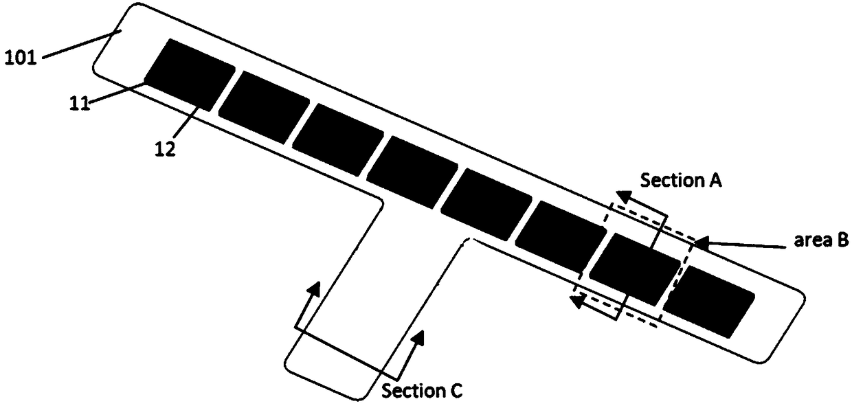
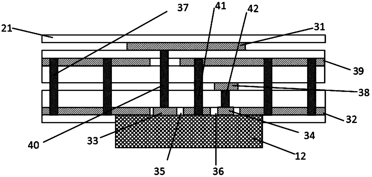
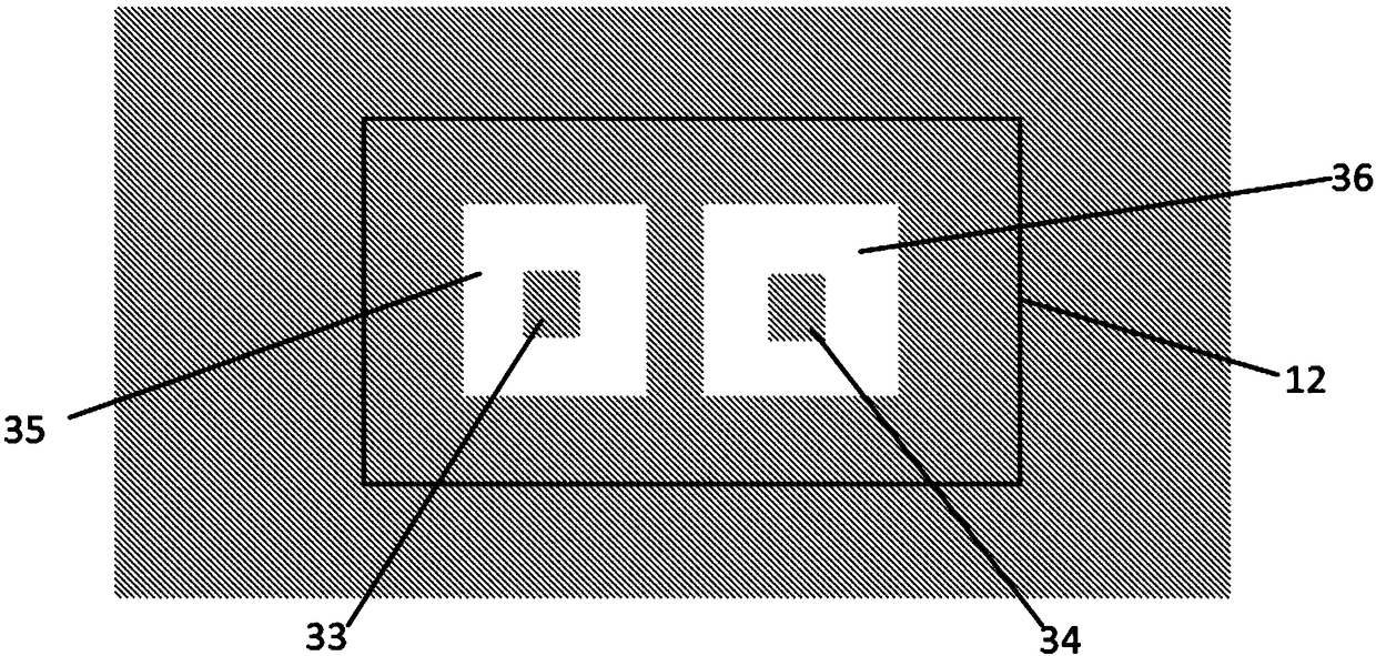
[0054] see figure 1 , figure 2 , image 3 as well as Figure 5 , a mobile terminal antenna module, including a substrate 101, a high-frequency antenna arranged on the substrate 101, and a signal processing module 12; wherein, the substrate 101 includes several conductor layers and several dielectrics covering the upper or lower surfaces of the several conductor layers Layer 21; the substrate 101 is placed on the side edge of the mobile terminal 62, placed vertical...


PUM


Abstract

The invention discloses a mobile terminal antenna module group comprising a substrate, a high-frequency antenna and signal processing modules. The substrate comprises multiple conductor layers and multiple dielectric layers. The high-frequency antenna comprises high-frequency antenna subunits. The signal processing modules and the high-frequency antenna subunits are consistent in number. Each high-frequency antenna subunit comprises a high-frequency antenna radiator and a high-frequency antenna reference ground. The high-frequency antenna radiators are arranged on the first conductor layer orsimultaneously arranged on other conductor layers. The high-frequency antenna reference grounds are arranged on the second conductor layer or simultaneously arranged on other conductor layers, and theconductor layers equipped with the high-frequency antenna reference grounds are electrically connected through first metalized through holes. The high-frequency antenna radiators and the high-frequency antenna reference grounds are electrically connected with the signal processing modules through a first feed line and a second feed line. The signal processing modules transmit the processed high-frequency antenna signals to a post-processing circuit through a third feed line and a signal transmission line.

Description

technical field [0001] The invention belongs to the field of mobile terminal antenna design, and in particular relates to a mobile terminal antenna module used in a 5G communication system. Background technique [0002] With the development of mobile communication technology and the full commercialization of 4G standard, the technical research and development targeting 4G standard has come to an end temporarily. On the other hand, the rapid development of smart phones has triggered a revolution in the rapid transfer of the Internet from fixed desktops to mobile terminals, and has brought about exponential growth in wireless data traffic. It is generally predicted in the industry that by 2020, the capacity demand of the mobile communication network will be 1000 times that of the current network, and the number of connections will be 10 to 100 times. The fifth-generation mobile communication (5G) for 2020 and the future has become a global research and development hotspot. ...

Claims


Application Information

Patent Timeline
Patent Type & Authority Applications(China)
IPC IPC(8): H01Q1/36H01Q1/38H01Q1/50
CPCH01Q1/36H01Q1/38H01Q1/50
Inventor 盘龙李立忠胡沥
Owner SHANGHAI AMPHENOL AIRWAVE COMM ELECTRONICS CO LTD
Learn More