
High -speed electric connector

An electrical connector, high-speed technology, applied in the direction of connection, parts of the connection device, circuits, etc., can solve the problems that cannot meet the high-speed requirements, cannot meet the high-speed requirements, etc., and achieve improved resonance, reduced loss, and signal integrity performance Enhanced effect

Active Publication Date: 2022-08-09
深圳市兴万联电子有限公司
View PDF17 Cites 0 Cited by
  • Summary
  • Abstract
  • Description
  • Claims
  • Application Information

AI Technical Summary

Problems solved by technology

[0003] Patent CN109004400 B discloses a combination of a card edge connector that uses a grounding piece to short-circuit the grounding terminal. This structure can meet the PCIE 4.0 transmission rate requirement of 16Gbps, but as the connector transmission rate becomes higher and higher, PCIE5.0 transmission The rate has reached 32Gbps, and the transfer rate of PCIE 6.0 has reached 64Gbps. This design can no longer meet such high-speed requirements
[0004] Patent CN 209183804 U is based on patent CN109004400 B and defines the contact point position of its grounding part. This design also cannot meet the requirements of higher speed

Method used


Image

  • High -speed electric connector
  • High -speed electric connector
  • High -speed electric connector

Examples


Embodiment Construction

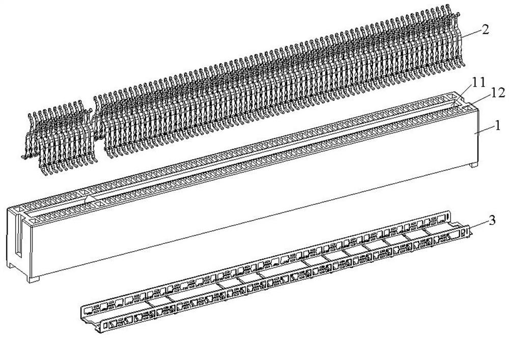
[0029] In order to facilitate a better understanding of the purpose, structure, features and effects of the present invention, the present invention will now be further described with reference to the accompanying drawings and specific embodiments.

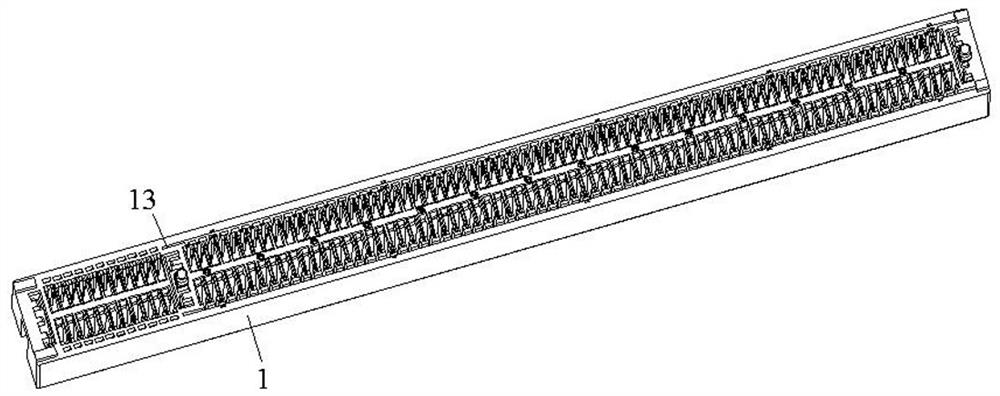
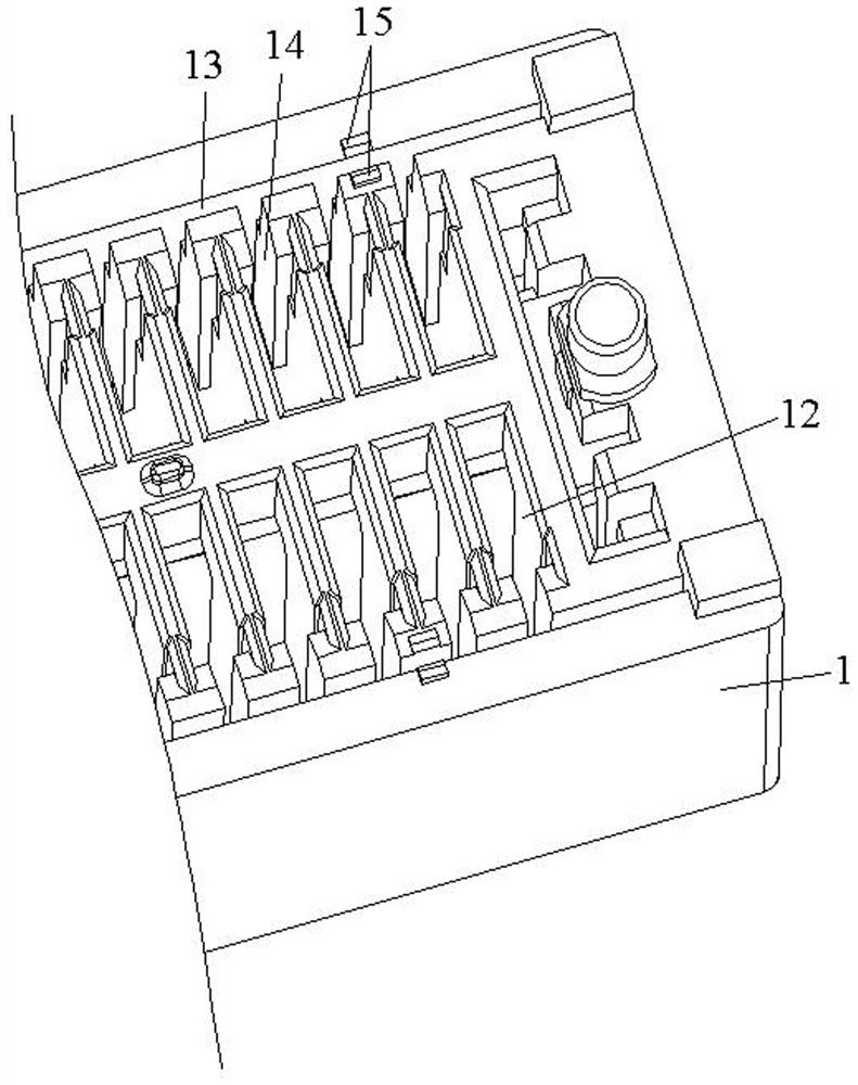
[0030] like Figure 1-10 As shown, the high-speed electrical connector of the present invention includes an insulating body 1 , a plurality of metal terminals 2 and a shielding member 3 fixed in the insulating body 1 .

[0031] The middle part of the top surface of the insulating body 1 is recessed along the longitudinal direction to form a central slot 11 , the two sides of the central slot 11 are provided with terminal accommodating holes 12 , and the two sides of the bottom surface of the insulating body 1 in the width direction are longitudinally extending along the insulating body 1 . The side receiving grooves 13 of the shielding member in the direction of the direction, and the insulating body 1 is also provided with a grou...


PUM


Abstract

The invention provides a high-speed electrical connector, comprising an insulating body, a plurality of metal terminals fixed in the insulating body, and a shielding member, wherein the metal terminal includes a plurality of ground terminals and a plurality of signal terminals, and the shielding member includes hollowed-out A bottom sheet and two side sheets in a state of ; The high-speed electrical connector improves the resonance in the high-frequency state, greatly reduces the loss of signal transmission, and greatly improves the signal integrity performance of the electrical connector, which can meet the needs of higher transmission rates.

Description

technical field [0001] The invention belongs to the field of connectors, in particular to a high-speed electrical connector. Background technique [0002] The transmission speed required by electronic and IT products is getting faster and faster, and the products must be compatible with the old version specifications at the same time when the products are updated. For example, for the PCIE slot connector, the physical interface standard of PCIE 4.0 and PCIE 5.0 has not changed. What has changed is that the transmission speed of PCIE 5.0 is directly doubled, which makes the connector design have higher requirements to meet the increase in transmission speed. . [0003] Patent CN109004400 B discloses a combination of a card edge connector using a grounding piece to short a grounding terminal. This structure can meet the requirements of the PCIE 4.0 transmission rate of 16 Gbps, but as the connector transmission rate requirements are getting higher and higher, the PCIE5.0 tran...

Claims


Application Information

Patent Timeline
Patent Type & Authority Patents(China)
IPC IPC(8): H01R13/6581H01R13/6471H01R13/652H01R12/72
CPCH01R13/6581H01R13/652H01R13/6471H01R12/721
Inventor 蔡友华林海燕彭龙强
Owner 深圳市兴万联电子有限公司
Learn More