Power-taking structure of electrolytic basin

A technology of electrolysis basin and electric contacts, which is applied in the direction of electrolysis process, electrolysis components, circuits, etc. It can solve the problems that electrolysis water involves water and electricity, the process of electrolysis water cannot be completed, and the safety problems of easy leakage

Pending Publication Date: 2018-06-19
PRIMY CORP LTD
View PDF7 Cites 1 Cited by
  • Summary
  • Abstract
  • Description
  • Claims
  • Application Information

AI Technical Summary

Problems solved by technology

[0006] Existing fruit and vegetable cleaning machines use electrolysis to obtain electrolyzed water to clean fruits and vegetables, but the electrolyzed water process requires electricity. If there is no stable power supply, the electrolyzed water process cannot be completed, and electrolyzed water involves water and electricity. If If water leaks into the power intake structure, it is easy to leak electricity and cause more serious safety problems. Therefore, it is necessary to have a safe, stable power intake structure that can isolate water to supply power to the electrolytic basin

Method used


Image

  • Power-taking structure of electrolytic basin
  • Power-taking structure of electrolytic basin
  • Power-taking structure of electrolytic basin

Examples


Embodiment Construction

[0026] In order to make the technical solution of the present invention clearer, the present invention will be described in detail below through specific embodiments in conjunction with the accompanying drawings.

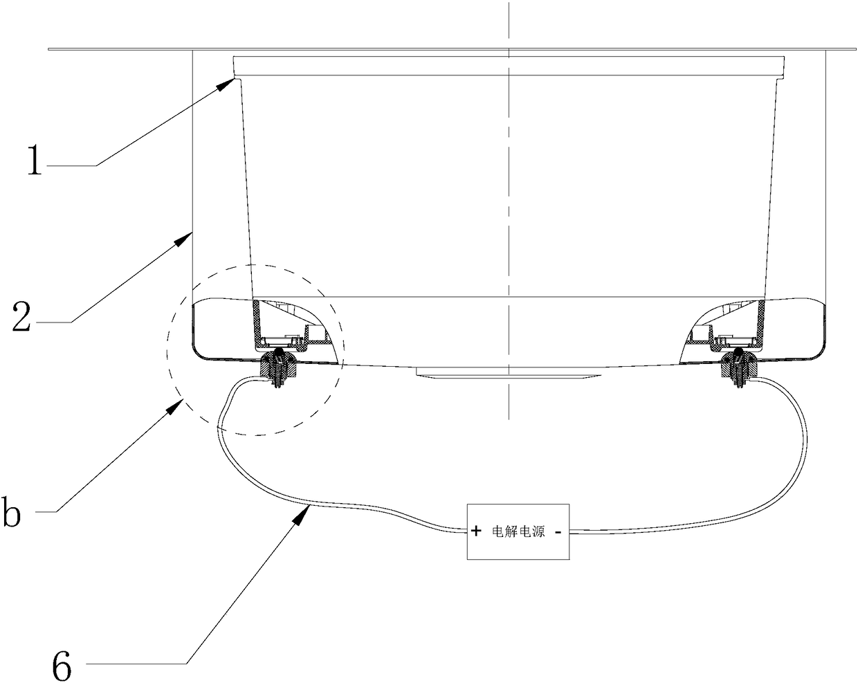
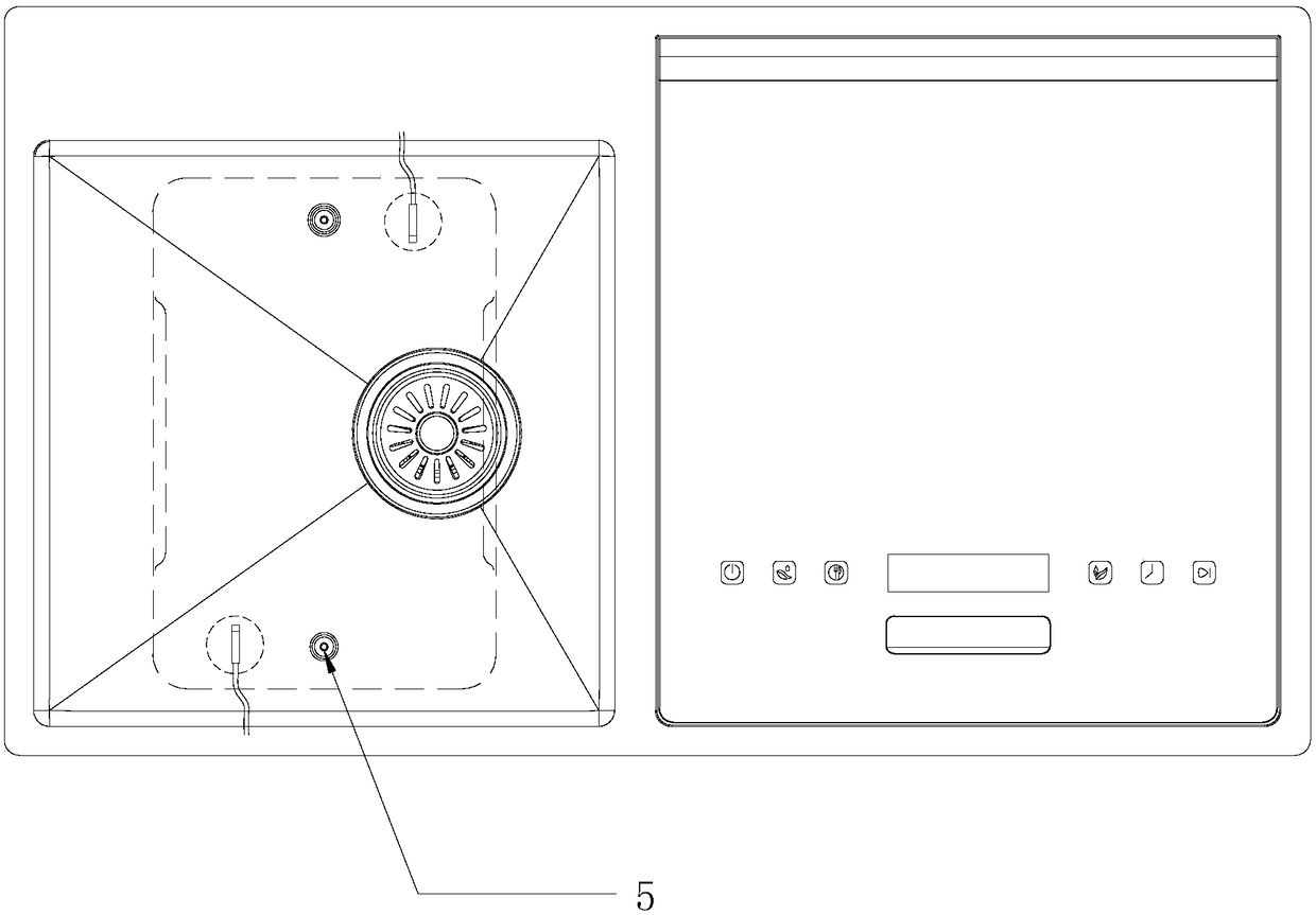
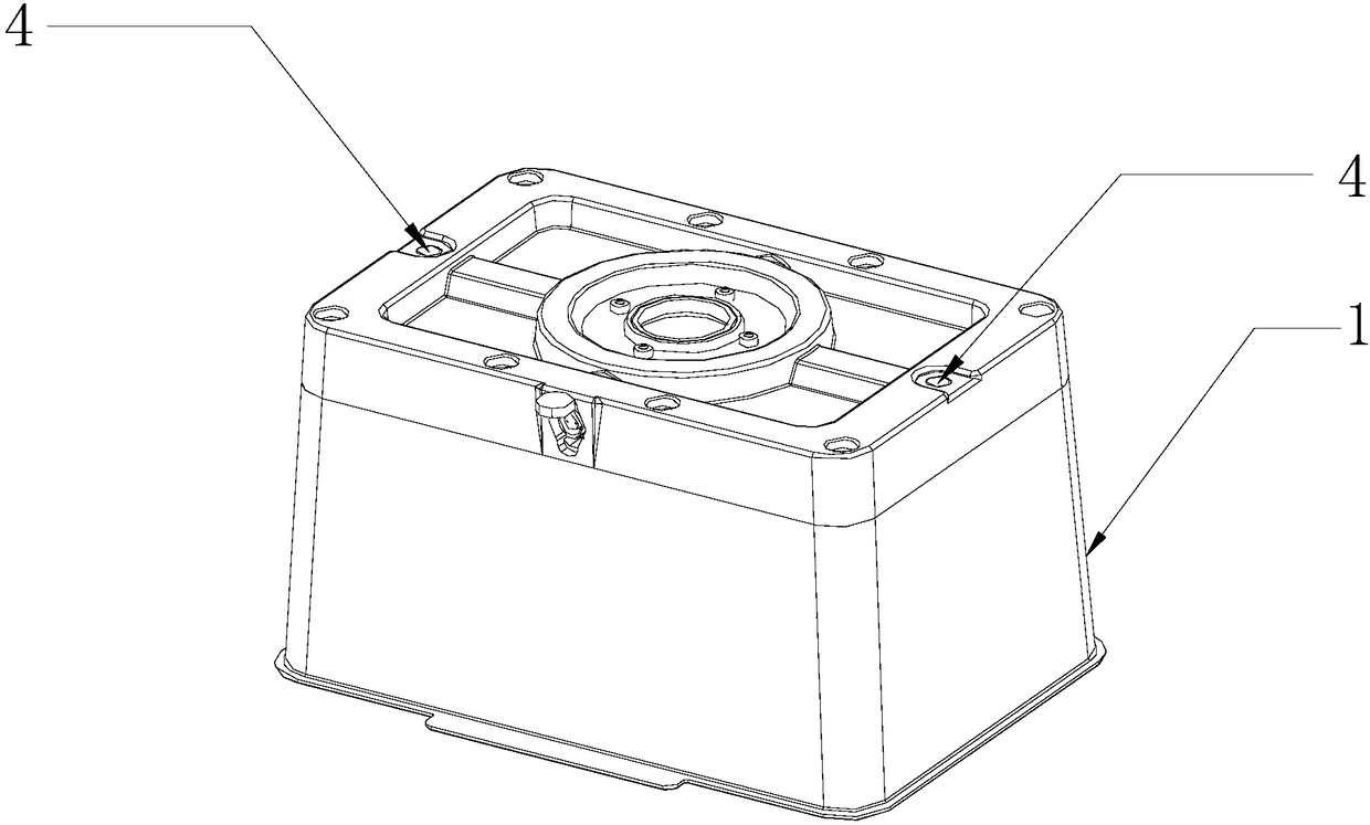
[0027] See Figure 1-Figure 6 , figure 1 It is a partial cross-sectional schematic diagram of the present invention; figure 2 It is a schematic top view of the water tank of the present invention. In order to show the assembly structure more clearly, the dotted line part in the figure is the electrolytic basin; image 3 It is the schematic diagram of electrolytic basin inversion of the present invention; Figure 4 is an enlarged schematic view of a part of the present invention; Figure 5 A schematic diagram of the overall structure of the electric contact for the water tank of the present invention; Image 6 It is a schematic diagram of the disassembled structure of the electric contact for the water tank of the present invention.

[0028] The power-taking st...


PUM


Abstract

The invention provides a power-taking structure of an electrolytic basin. The invention relates to the field of fruit and vegetable cleaning and particularly relates to a power-taking structure of anelectrolytic basin. The power-taking structure comprises the electrolytic basin and a water tank, the bottom of the electrolytic basin is provided with a water tank power-taking contact piece, the water tank is provided with a groove for assembling the electrolytic basin, a bottom wall corresponding position of the groove is provided with a water tank power-taking contact point matched with the water tank power-taking contact piece, the water tank power-taking contact point is connected to a conductive wire which is connected to two ends of a power supply, a circuit is switched on when the water tank power-taking contact piece and the water tank power-taking contact point are in match contact, and the electrolytic basin is powered to start working. The power-taking structure has the advantages that stable power can be provided to the electrolytic basin, and the requirements of safety, stability and water isolation can be satisfied.

Description

technical field [0001] The invention relates to the field of fruit and vegetable cleaning, in particular to a power-taking structure of an electrolytic basin. Background technique [0002] With the continuous improvement of living standards, people's requirements for nature, nutrition and health are also getting higher and higher. Fresh fruits and vegetables are rich in vitamins, minerals, antioxidants and anti-aging ingredients, so they are favored by consumers. However, when using the existing household terminal tap water to wash fruits and vegetables, the existing household terminal tap water itself has pollution. At the same time, the residual pesticides and toxic heavy metals or inorganic substances in the fruits and vegetables are inconvenient to eat. In order to degrade pollutants in fruits and vegetables, the following two types are generally used: [0003] Mechanical fruit and vegetable cleaning machine: It uses water circulation washing method or ultrasonic vibra...

Claims


Application Information

Patent Timeline
Patent Type & Authority Applications(China)
IPC IPC(8): H01R13/02H01R13/24H01R13/52H01R24/00C02F1/461C25B9/04
CPCH01R13/02H01R13/2421H01R13/2478H01R13/52H01R13/5202H01R13/521H01R24/00C02F1/46104C02F2201/46105C02F2201/4616C25B9/65
Inventor 卫凯·提鲁那嘎鲁周黎明邵婷婷刘勇
Owner PRIMY CORP LTD
Why Eureka
Try Eureka