Laser beam multi-dimensional precision adjustment device integrating active heat dissipation structure

A laser beam, active heat dissipation technology, applied in laser cooling devices, lasers, laser parts and other directions, can solve the problems of beam adjustment, interference, installation, equipment necrosis, inability to work, etc., and achieve reliable laser output. , to ensure stability and increase the effect of heat exchange area

Pending Publication Date: 2018-06-19
武汉晟诺仪器科技有限公司
View PDF0 Cites 3 Cited by
  • Summary
  • Abstract
  • Description
  • Claims
  • Application Information

AI Technical Summary

Problems solved by technology

However, various problems are still emerging one after another, and cannot fundamentally solve the problems of beam adjustment, interference, installation, etc.
The spring of the adjustment device is deformed after the temperature rises, and the emission angle of the original laser beam on board changes, and the equipment is completely in a state of necrosis and cannot work
It can be seen that the existing similar adjustment devices on the market cannot meet the needs in actual production at all, and due to various inconveniences and many unexpected situations and events, unnecessary manpower, material and financial resources are generated.

Method used


Image

  • Laser beam multi-dimensional precision adjustment device integrating active heat dissipation structure
  • Laser beam multi-dimensional precision adjustment device integrating active heat dissipation structure
  • Laser beam multi-dimensional precision adjustment device integrating active heat dissipation structure

Examples


Embodiment Construction

[0033] The present invention will be described in further detail below in conjunction with specific examples.

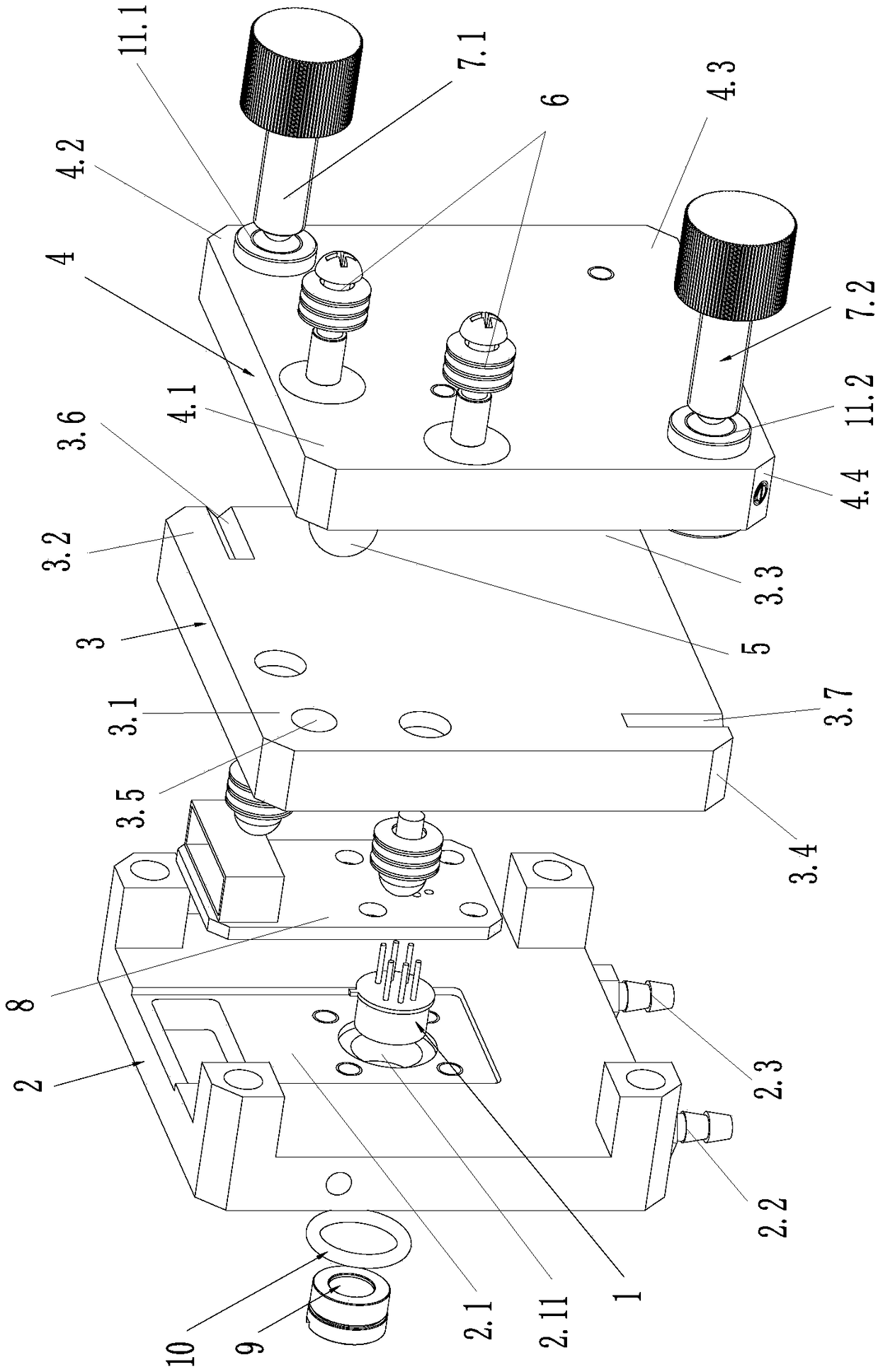
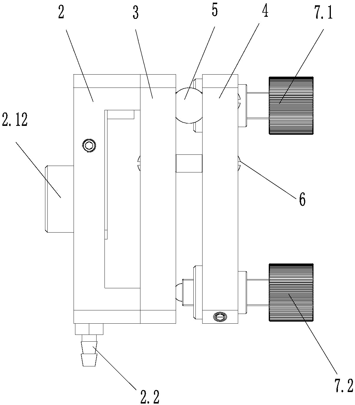
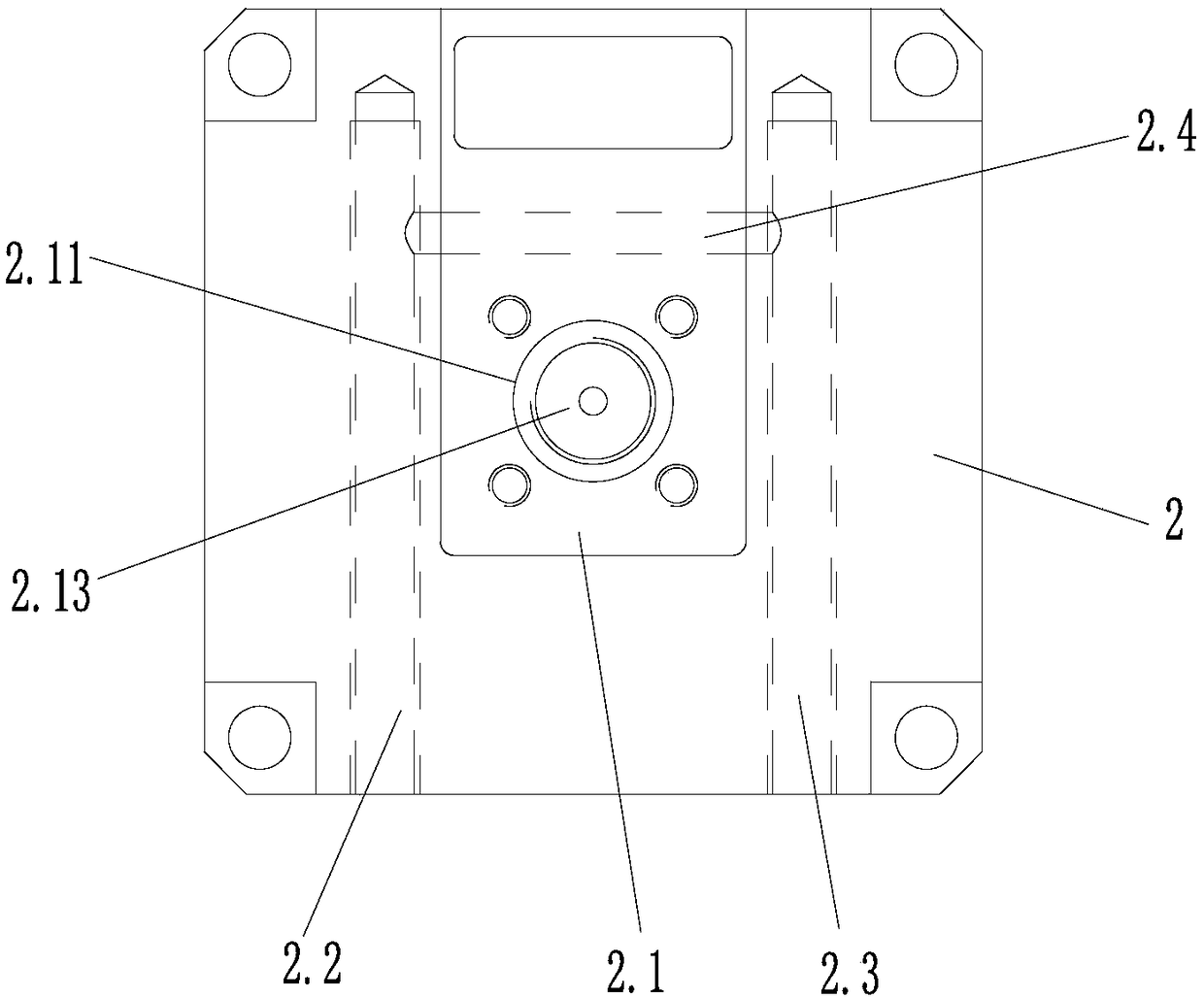
[0034] Such as figure 1 and figure 2 A laser beam multi-dimensional precision adjustment device with an integrated active heat dissipation structure is shown, including a laser 1, and a base 2 arranged in sequence along the beam propagation direction for installing the laser 1 and having a self-heating function, and a base 2 for fixed connection with the base 2. The rotating base 3 used to adjust the position of the laser spot, and the fixed base 4 that is relatively rotatable connected with the rotating base 3; the base 2, the rotating base 3, and the fixing base 4 are all treated in a special way to black the surface of the parts, effectively avoiding the occurrence of laser damage. The light is reflected and scattered between the parts, so as to avoid the interference phenomenon of the laser caused by the stray light of the parts.

[0035] The swivel seat 3 has...


PUM


Abstract

The invention discloses a laser beam multi-dimension precise adjusting device integrating an active heat dissipation structure. The device includes a laser, a base with a self-heat dissipation function, a rotating seat for adjusting a laser spot position, and a fixing seat; a transverse sliding groove is formed at the second corner of the rotating seat; a first adjustment rotation rod is formed atthe second corner area of the fixing seat, wherein the first adjustment rotation rod abuts against the transverse sliding groove and is used for driving the rotating seat to rotate relative to the fixing seat with a ball adopted a rotation fulcrum, so that the laser spot can move leftwards and rightwards along a transverse direction; a vertical sliding groove is formed at the fourth corner of therotating seat; and a second adjustment rotation rod is formed at the fourth corner area of the fixing seat, wherein the second adjustment rotation rod abuts against the vertical sliding groove and isused for driving the rotating seat to rotate relative to the fixing seat with the ball adopted the rotation fulcrum, so that the laser spot can move up and down along a vertical direction. The laserbeam multi-dimension precise adjusting device integrating the active heat dissipation structure of the invention is compose of precise mechanical transmission devices on the basis of optical technologies. With the laser beam multi-dimension precise adjusting device integrating the active heat dissipation structure of the invention adopted, the installation, debugging and use of laser beams under any temperature and angle conditions can be realized.

Description

technical field [0001] The invention relates to a laser beam adjustment device, in particular to a multi-dimensional precision adjustment device for a laser beam integrated with an active heat dissipation structure. Background technique [0002] With the continuous acceleration of people's life rhythm and the continuous improvement of living standards, environmental pollution, prevention, governance and improvement have become an indispensable part of people's lives. Such as: continuous monitoring of gas, laser processing and production, etc. The adjustment of the laser beam has become a necessary component of various laser equipment. All kinds of analysis and testing instruments, production and processing equipment are all in good condition through optical adjustment, so that they can work and run on their equipment and instruments. [0003] Although there are various imported and domestically produced adjustment devices used in the current market, their adjustment device...

Claims


Application Information

Patent Timeline
Patent Type & Authority Applications(China)
IPC IPC(8): H01S3/04H01S3/02
CPCH01S3/04H01S3/02H01S3/0404
Inventor 乐聪林蒋泰毅蔡磊
Owner 武汉晟诺仪器科技有限公司
Why Eureka
Try Eureka