
Wear-resistant highly heat-conducting sheet and application thereof

A technology with high thermal conductivity and friction resistance, which is applied in the field of materials to achieve the effect of improving interface thermal resistance, improving wear resistance, and satisfying plugging friction

Inactive Publication Date: 2018-06-19
SHANGHAI ALLIED PLASTIC IND
View PDF7 Cites 2 Cited by
  • Summary
  • Abstract
  • Description
  • Claims
  • Application Information

AI Technical Summary

Problems solved by technology

There is currently no material that can meet the above three requirements

Method used


Image

  • Wear-resistant highly heat-conducting sheet and application thereof
  • Wear-resistant highly heat-conducting sheet and application thereof

Examples


Embodiment Construction

[0030] In order to make the technical means, creative features, goals and effects achieved by the present invention easy to understand, the present invention will be further described below in conjunction with specific diagrams.

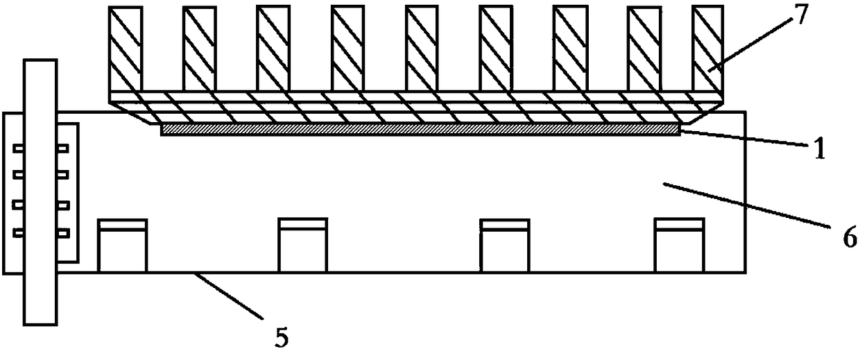
[0031] refer to figure 1 , figure 2 , a friction-resistant high thermal conductivity sheet, including a thermal conductivity layer 2 located above, the thermal conductivity layer 2 is made of a thermal conductivity material with a thermal conductivity greater than 2W / m-K; it also includes a wear-resistant layer 4 located below, and the wear-resistant layer 4 is made of Made of wear-resistant material with a thermal conductivity greater than 0.3W / m-K; the wear-resistant layer 4 is fixed under the heat-conducting layer 2 . The invention improves the wear-resistant performance through the wear-resistant layer, and at the same time utilizes the heat-conducting layer protected by the wear-resistant layer to improve the interface thermal resistance. At ...


PUM


Abstract

The invention provides a wear-resistant highly heat-conducting sheet and application thereof and relates to a heat-conducting material. The wear-resistant highly heat-conducting sheet comprises a heat-conducting layer which is located above and is made of a heat-conducting material with a heat conductivity coefficient larger than 2 W / m-K, and a wear resistant layer which is located below and is made of a wear resistant material with a heat conductivity coefficient larger than 0.3 W / m-K, and the wear resistant layer is fixed under the heat-conducting layer. The wear resistance performance is improved by the wear resistant layer, and at the same time the heat-conducting layer protected by the wear resistant layer is used to improve interface thermal resistance. A plugging resistant connectorwith the wear-resistant highly heat-conducting sheet is the application of the wear-resistant highly heat-conducting sheet in the connector.

Description

technical field [0001] The invention relates to materials, in particular to a thermally conductive material. Background technique [0002] With the upgrading of communication networks, the optical communication industry requires higher and higher data transmission volumes, and with the popularization of laser chip-level applications, the specifications of optical modules are developing towards 10 Gigabit and above, and at the same time, the size of equipment is developing towards miniaturization. High integration leads to high heat generation, which brings the challenge of overheating in the equipment operating environment. In the traditional solution, the heat sink of the device directly contacts the photoelectric conversion module, and the heat generated from the chip needs to pass through the optical module shell and the gap between the heat sink and the path from the chip to the heat sink. If you want to improve the heat transfer efficiency from the chip to the radiator...

Claims


Application Information

Patent Timeline
IPC IPC(8): H05K7/20C09J7/29C09J7/20
CPCH05K7/2039
Inventor 李延民
Owner SHANGHAI ALLIED PLASTIC IND
Learn More