Uterine cavity support

A technology of uterine cavity and uterine ring, which is applied in the field of uterine cavity stents used in gynecology, can solve the problems of affecting the curative effect, not well preventing and controlling adhesions, and the effect of preventing and controlling intrauterine adhesions is not good, and achieves the effect of good support.

Inactive Publication Date: 2018-06-22
徐大宝
View PDF3 Cites 2 Cited by
  • Summary
  • Abstract
  • Description
  • Claims
  • Application Information

AI Technical Summary

Problems solved by technology

The uterine cavity stent disclosed in Chinese patent ZL201611271206.3 focuses on the prevention and treatment of intrauterine adhesions above the lower segment of the uterine cavity. In actual clinical work, there are often patients with adhesions in the lower segment of the uterus. However, this type of uterine ring is due to its Anatomically, it is difficult to cover the adhesion position of such patients, resulting in poor final prevention and treatment of intrauterine adhesions; Chinese patent ZL201420415502.6 highlights the design of the tail, but its structure does not match the triangle shape of the lower uterine segment, and cannot adapt to different patients The actual situation of intrauterine adhesions; the Chinese patent ZL201220070407.8 uterine cavity stent-specific S-shaped film design can better drain intrauterine fluid, but the part of the uterine cavity that is not covered with a film in the center does not prevent adhesions well, thus affecting Final curative effect

Method used


Image

  • Uterine cavity support

Examples


Embodiment Construction

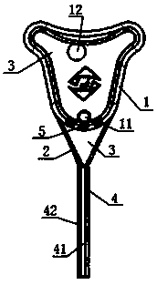
[0016] The following will combine figure 1 The present invention is described in detail, and the exemplary embodiments and descriptions of the present invention are used to explain the present invention, but not to limit the present invention.

[0017] A uterine cavity bracket, including a uterine ring 1 whose upper end can extend into the uterine cavity and is formed according to the shape of the inner wall of the uterine cavity. The uterine ring is made of elastic material, and its hardness is 50-70HRC. If the uterine ring is too hard, it will cause It is not easy to put into the uterine cavity, even if it is barely put into the uterine cavity, it will compress the tissue in the uterus and cause damage to the human body; but within the hardness range of 50-70HRC, it can ensure that the cervix ring can be deformed when it passes through the cervix, and it can reach The uterine cavity can quickly return to the same shape as the outline of the uterine cavity, so as to effective...


PUM


Abstract

The invention relates to a uterine cavity support. The uterine cavity support comprises a uterus-shaped ring of which the upper end can stretch into the uterine cavity and which is formed in the shapeof the inner wall of the uterine cavity, and a connecting ring formed in the shape of the periphery of the lower section of the uterus is arranged at the lower end of the uterus-shaped ring; the uterus-shaped ring is made of an elastic material, and the harness of the uterus-shaped ring is 50-70 HRC; thin film is arranged in both the inner ring of the uterus-shaped ring and the inner ring of theconnecting ring. The uterus-shaped ring of the uterine cavity support cannot harm the human body, the uterus-shaped ring, the connecting ring and the thin film can effectively prevent the front wall and the rear wall, the two side walls and the two side uterine corners of the uterine cavity and the lower section of the uterus from adhering to one another again; the hardness of the uterus-shaped ring can guarantee that the uterus-shaped ring can well pass through the cervix uteri, arrive at the uterine cavity and can be well attached to the periphery of the inner wall of the uterus, and a verygood supporting effect is achieved on the uterine cavity.

Description

technical field [0001] The invention relates to the field of medical devices, in particular to a uterine cavity bracket for gynecology. Background technique [0002] Intrauterine adhesions are the pathological phenomenon of partial or complete adhesions due to damage to the endometrium of the uterus, such as induced abortion, uterine curettage after drug abortion, mid-term induction of labor or full-term postpartum evacuation, non-pregnant uterine diagnostic curettage, uterine myomectomy Surgery, submucosal myomectomy, hysteroscopic endometrial resection, etc. will cause intrauterine adhesions, usually lead to abnormal menstruation, such as hypomenorrhea or amenorrhea, etc., patients are prone to miscarriage, premature delivery, ectopic pregnancy, Intrauterine fetal death, placenta accreta, placental adhesions and even infertility or intrauterine hemorrhage. At present, the treatment of intrauterine adhesions is generally divided into four links: ① Surgical treatment: stand...

Claims


Application Information

Patent Timeline
Patent Type & Authority Applications(China)
IPC IPC(8): A61B17/42A61F2/82A61M1/00
CPCA61B17/4241A61B2017/4216A61F2/82A61M1/0023
Inventor 徐大宝朱修婷
Owner 徐大宝
Why Eureka
Try Eureka