Deburring mechanism

A technology of deburring mechanism and guide rails, applied in mechanical equipment, gear teeth, grinding machines, etc., can solve problems such as damage to workpieces, iron filings endangering the safety of workers, and deburring discs cannot be completely fitted, etc., to improve the grinding effect and stress Uniform and safe effect

Inactive Publication Date: 2018-06-22
CHONGQING SHUNHUAI MACHINERY MFG CO LTD
View PDF7 Cites 1 Cited by
  • Summary
  • Abstract
  • Description
  • Claims
  • Application Information

AI Technical Summary

Problems solved by technology

[0005] The purpose of the present invention is to provide a deburring mechanism to solve the problem that the deburring plate cannot be completely attached to the processing end surface of the workpi

Method used


Image

  • Deburring mechanism
  • Deburring mechanism

Examples


Embodiment Construction

[0018] The present invention will be described in further detail below by means of specific embodiments:

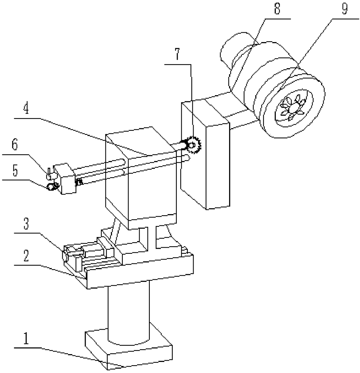
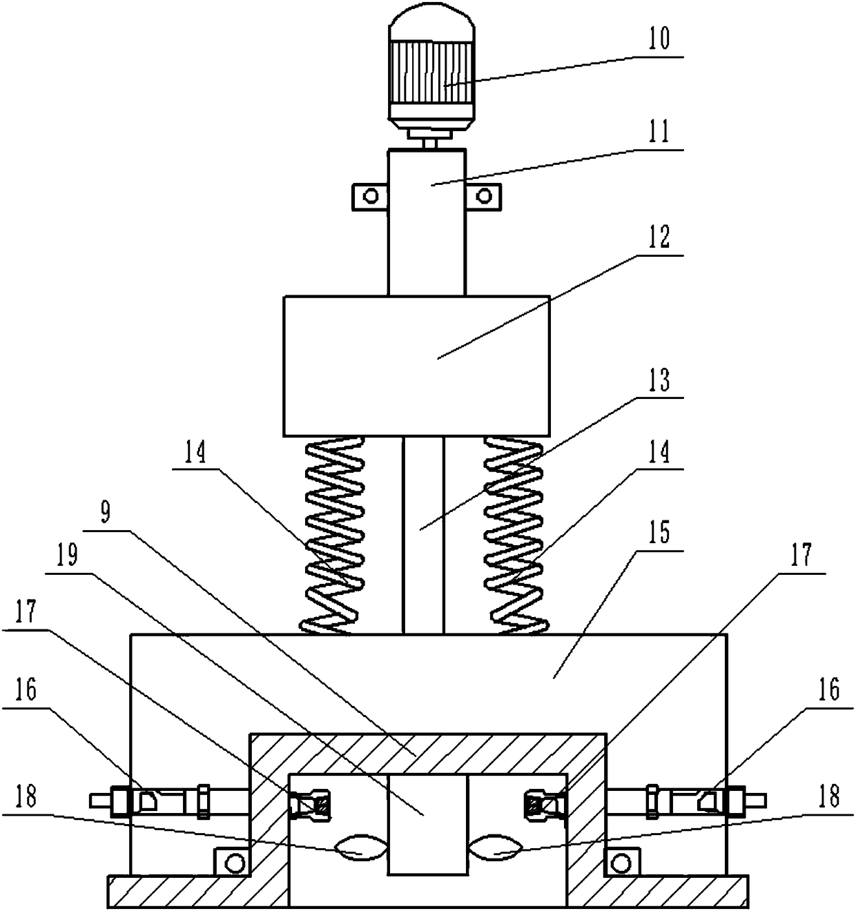
[0019] Instructions attached Figures 1 to 2 The reference signs in include: supporting column 1, adjusting guide rail 2, adjusting lead screw 3, guide rail seat 4, guide rail 5, worm screw 6, worm wheel 7, deburring disc seat 8, deburring disc 9, drive motor 10, input shaft 11. Disc 12, flexible shaft 13, spring 14, fixed seat 15, rotary joint 16, check valve 17, fan blade 18, drive shaft 19.

[0020] Such as figure 1 As shown, a deburring mechanism includes a support column 1, an adjustment guide rail 2 is installed on the upper end of the support column 1, an adjustment screw 3 is installed on the left end of the adjustment guide rail 2, a guide rail seat 4 is installed on the upper end of the adjustment guide rail 2, and the adjustment screw 3 and Described guide rail seat 4 forms leading screw nut mechanism, and the side wall of guide rail seat 4 is equipped with g...


PUM


Abstract

The invention belongs to the technical field of machining equipment, and particularly discloses a deburring mechanism. The deburring mechanism comprises a support column, and an adjustment guide railis mounted on the upper end of the support column; a guide rail seat is mounted on the upper end of the adjustment guide rail, and a guide rail is arranged on the guide rail seat in a penetrating mode; a nut mechanism is installed at one end of the guide rail, and a deburring disc seat is installed at the other end of the guide rail; the deburring disc seat comprises a drive motor, and the drive motor is sequentially connected with an input shaft, a flexible shaft and a transmission shaft; the input shaft is sleeved with a disc, and the input shaft is connected with the flexible shaft; the transmission shaft is sleeved with a fixing seat, and a plurality of springs are arranged between the disc and the fixing seat; a deburring disc is connected to the transmission shaft, and the deburringdisc is rotatably connected with the fixing seat; a recessed cavity is formed inside the deburring disc, and one end of the transmission shaft extends into the recessed cavity and is provided with fanblades; and the side wall of the recessed cavity is symmetrically provided with one-way valves, the fixing seat is provided with rotating joints in a penetrating mode, and a protective disk is arranged on the periphery of the deburring disc. According to the technical scheme, burrs on the surfaces of workpieces can be effectively removed, and the safety of workers during the operation can be ensured at the same time.

Description

technical field [0001] The invention belongs to the technical field of mechanical processing equipment, and in particular relates to a deburring mechanism. Background technique [0002] In the field of mechanical processing, during the processing of the workpiece, there are often many mechanical burrs on the outer surface of the workpiece. The burr refers to the extremely fine microscopic metal particles on the surface of the workpiece, which are formed during cutting, grinding, milling and other similar chip processing. formed in the process. If the burrs on the surface of the workpiece are not removed, not only will the precision of the product be affected, but workers will be easily scratched during operation. In the prior art, the manual method is usually used to remove the burrs on the surface of the workpiece by using a file or a hammer. This method has low work efficiency and high work intensity. [0003] In order to solve the above problems, the Chinese patent appl...

Claims


Application Information

Patent Timeline
IPC IPC(8): B23F19/00B24B27/033
CPCB23F19/00B24B27/033
Inventor 刘险峰
Owner CHONGQING SHUNHUAI MACHINERY MFG CO LTD
Why Eureka
Try Eureka