Cutting device for rubber

A cutting device and rubber technology, applied in metal processing and other directions, can solve the problems of time-consuming, labor-intensive, high-cost, and achieve the effect of convenient and quick operation.

Active Publication Date: 2018-06-22
CHANGSHA YONGCHANG AUTOMOBILE PARTS
View PDF4 Cites 12 Cited by
  • Summary
  • Abstract
  • Description
  • Claims
  • Application Information

AI Technical Summary

Problems solved by technology

[0005] In order to overcome the existing disadvantages that the rubber is cut manually, the labor intensity is high, the work efficiency is low, time-consuming and laborious, the cost is high, the expenditure is large, and the funds are wasted seriously, the technical problem to be solved by the invention is to provide a kind of cutting device

Method used


Image

  • Cutting device for rubber
  • Cutting device for rubber
  • Cutting device for rubber

Examples


Embodiment 1

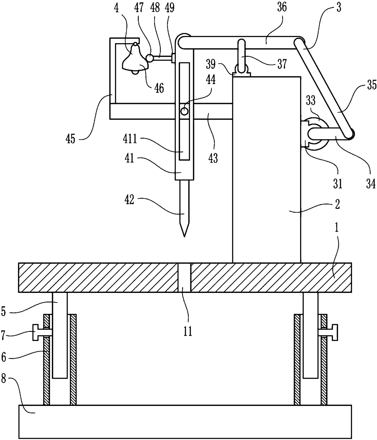
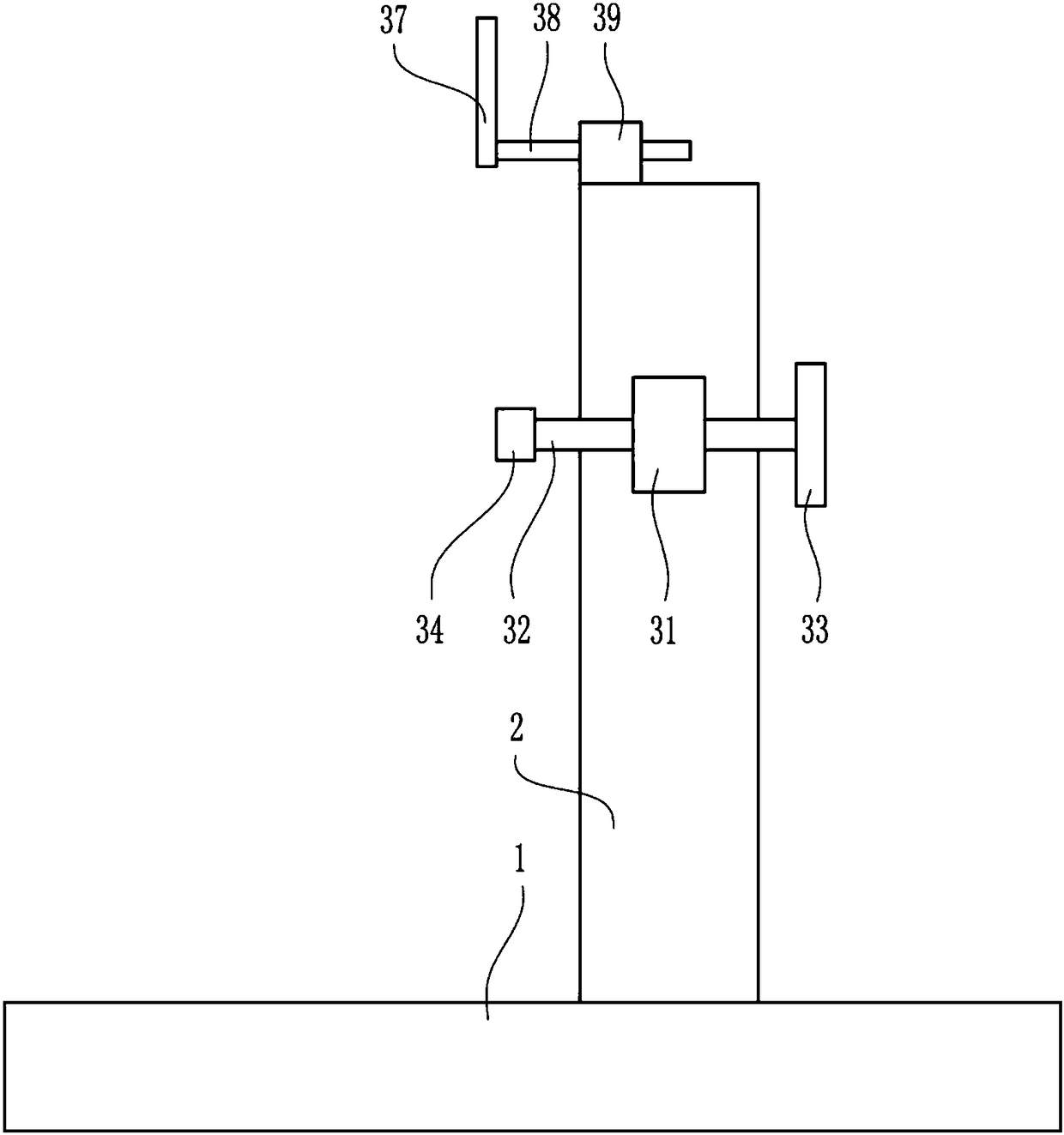
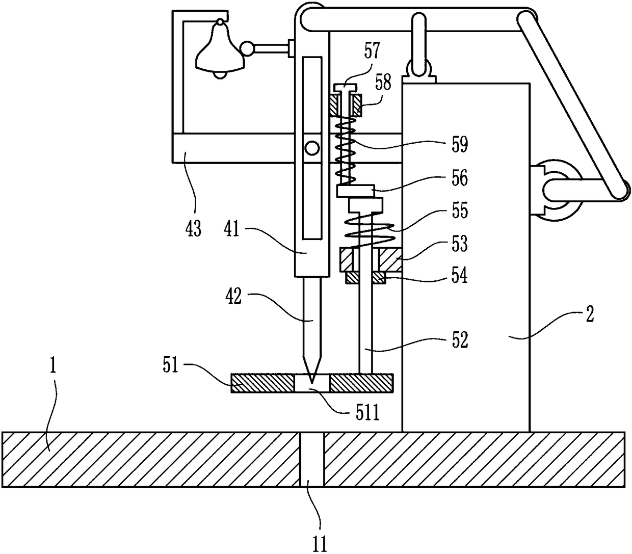
[0032] A cutting device for rubber, such as Figure 1-6 As shown, it includes a workbench 1, a large fixed plate 2, a driving device 3, a cutting device 4, an elevating rod 5, a sleeve 6, a positioning screw 7 and a base 8; the large fixed plate 2 is located above the workbench 1, and the large fixed plate The plate 2 and the worktable 1 are fixedly connected, the large fixed plate 2 is provided with a driving device 3, the cutting device 4 is located on the left side of the large fixed plate 2, the lifting rod 5 is located under the workbench 1, and the lifting rod 5 is connected to the workbench. 1 is set as a fixed connection, the lifting rod 5 is slidingly located in the casing 6, and the side wall of the casing 6 is provided with a positioning screw 7, and the positioning screw 7 and the casing 6 are set as threaded connections, and the positioning screw 7 and the lifting rod 5 In contact with each other, the lifting rod 5, the casing 6 and the positioning screw 7 are arr...

Embodiment 2

[0034] A cutting device for rubber, such as Figure 1-6 As shown, it includes a workbench 1, a large fixed plate 2, a driving device 3, a cutting device 4, an elevating rod 5, a sleeve 6, a positioning screw 7 and a base 8; the large fixed plate 2 is located above the workbench 1, and the large fixed plate The plate 2 and the worktable 1 are fixedly connected, the large fixed plate 2 is provided with a driving device 3, the cutting device 4 is located on the left side of the large fixed plate 2, the lifting rod 5 is located under the workbench 1, and the lifting rod 5 is connected to the workbench. 1 is set as a fixed connection, the lifting rod 5 is slidingly located in the casing 6, and the side wall of the casing 6 is provided with a positioning screw 7, and the positioning screw 7 and the casing 6 are set as threaded connections, and the positioning screw 7 and the lifting rod 5 In contact with each other, the lifting rod 5, the casing 6 and the positioning screw 7 are arr...

Embodiment 3

[0037] A cutting device for rubber, such as Figure 1-6 As shown, it includes a workbench 1, a large fixed plate 2, a driving device 3, a cutting device 4, an elevating rod 5, a sleeve 6, a positioning screw 7 and a base 8; the large fixed plate 2 is located above the workbench 1, and the large fixed plate The plate 2 and the worktable 1 are fixedly connected, the large fixed plate 2 is provided with a driving device 3, the cutting device 4 is located on the left side of the large fixed plate 2, the lifting rod 5 is located under the workbench 1, and the lifting rod 5 is connected to the workbench. 1 is set as a fixed connection, the lifting rod 5 is slidingly located in the casing 6, and the side wall of the casing 6 is provided with a positioning screw 7, and the positioning screw 7 and the casing 6 are set as threaded connections, and the positioning screw 7 and the lifting rod 5 In contact with each other, the lifting rod 5, the casing 6 and the positioning screw 7 are arr...


PUM


Abstract

The invention relates to a cutting device, in particular to a cutting device for rubber. The cutting device for the rubber includes a working table, a large fixing plate, a driving device, a cutting device, a lifting rod, a sleeve and the like; the large fixing plate is fixedly connected with the working table, the large fixing plate is provided with the driving device, and the cutting device is located at the left side of the large fixing plate; the lifting rod is located below the working table, the lifting rod is fixedly connected with the working table, and the lifting rod is slidably located in the sleeve; and the side wall of the sleeve is provided with a locating screw which is connected with the sleeve in a thread mode. According to the cutting device for the rubber, the driving device and the cutting device are arranged to conveniently and fast cut the rubber, the cutting efficiency is high, the effect is good, the labor intensity is low, and time and labor can be saved.

Description

technical field [0001] The invention relates to a cutting device, in particular to a cutting device for rubber. Background technique [0002] Rubber refers to a highly elastic polymer material with reversible deformation. It is elastic at room temperature, can produce large deformation under a small external force, and can return to its original shape after the external force is removed. Rubber is a completely amorphous polymer with a low glass transition temperature and often a large molecular weight, greater than hundreds of thousands. Early rubber was latex taken from plants such as rubber trees and rubber grasses, which were processed into materials with elasticity, insulation, impermeability to water and air. High elastic polymer compound. Divided into two kinds of natural rubber and synthetic rubber. Natural rubber is processed by extracting gum from rubber trees, rubber grass and other plants; synthetic rubber is obtained by polymerization of various monomers. Rub...

Claims


Application Information

Patent Timeline
Patent Type & Authority Applications(China)
IPC IPC(8): B26D1/08B26D5/14B26D7/22B26D7/02B26D7/32
Inventor 胡武平王天翔王彤
Owner CHANGSHA YONGCHANG AUTOMOBILE PARTS
Why Eureka
Try Eureka