
Double-rotor motor and multi-shaft cascaded electromechanical coupling structure for hybrid electric vehicle

A dual-rotor motor and outer rotor technology, which is applied to the arrangement of multiple prime movers and motors of electric vehicles and general power plants, can solve the problem of slow development of hybrid vehicles, complex mechanisms, and incomplete characteristics of dual-rotor motors. Issues such as playing out, to achieve the effect of improving mechanism reuse rate and power density, improving safety, and fast acceleration and deceleration

Active Publication Date: 2018-06-22
CHONGQING JIAOTONG UNIVERSITY
View PDF7 Cites 0 Cited by
  • Summary
  • Abstract
  • Description
  • Claims
  • Application Information

AI Technical Summary

Problems solved by technology

Although domestic research on hybrid power transmission system has been more in recent years, due to the restriction of foreign patents, there are few mature products, which has also led to the slow development of hybrid electric vehicles in my country; and in the existing technology, the electromechanical coupling scheme The dual-rotor motor only decouples the speed, and decouples the torque through another motor. Although its combination with the clutch provides more working modes, it also causes the mechanism to be too complicated, making the dual-rotor motor Features not fully exploited

Method used


Image

  • Double-rotor motor and multi-shaft cascaded electromechanical coupling structure for hybrid electric vehicle
  • Double-rotor motor and multi-shaft cascaded electromechanical coupling structure for hybrid electric vehicle
  • Double-rotor motor and multi-shaft cascaded electromechanical coupling structure for hybrid electric vehicle

Examples


Embodiment Construction

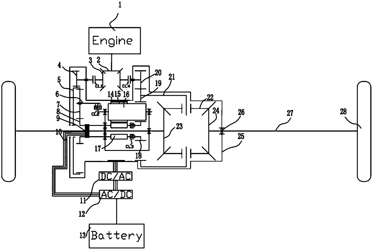
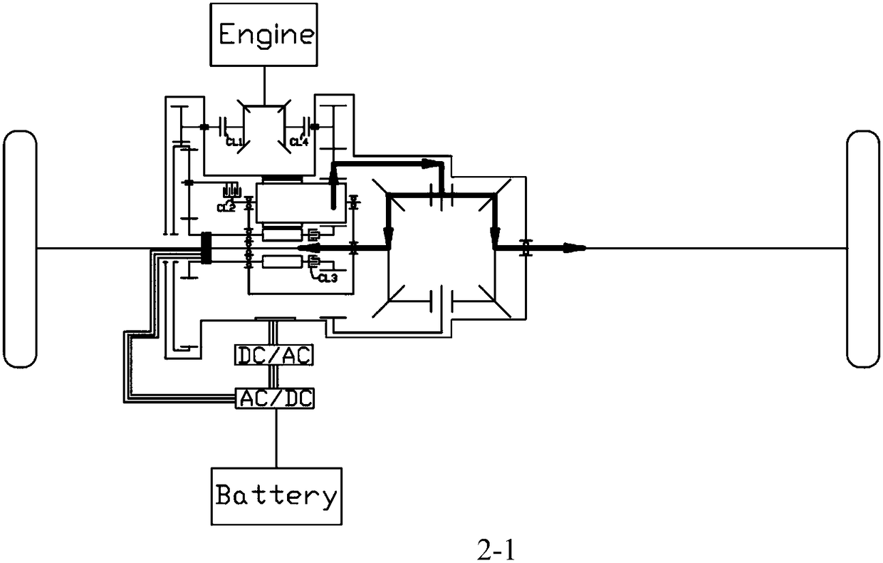
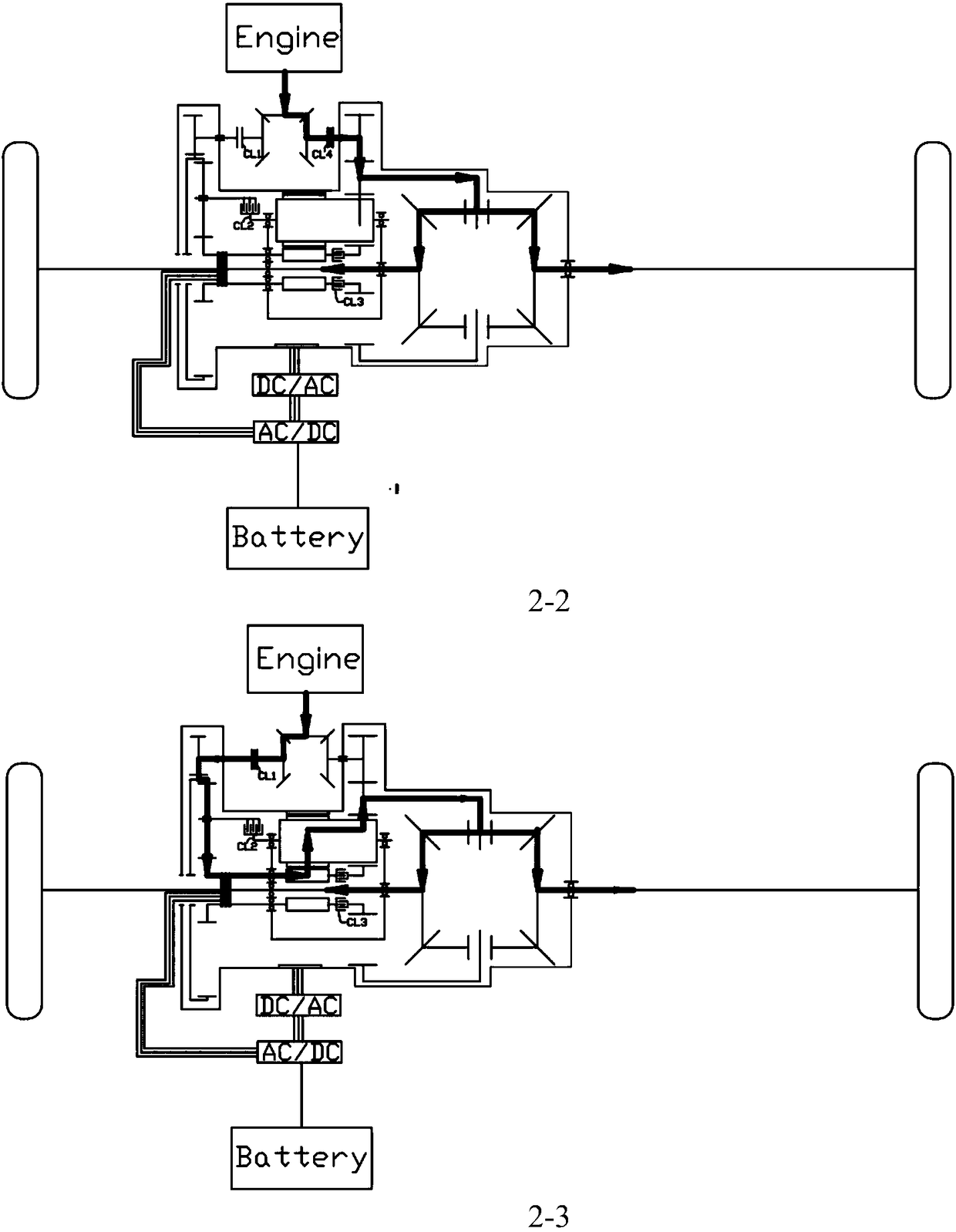
[0017] figure 1 It is a structural schematic diagram of the present invention, figure 2 It is the power flow diagram of several main modes of the present invention; as shown in the figure, the dual-rotor motor in this embodiment includes a stator 14, an inner rotor 17 coaxially rotated and installed in the stator 14, and is set in a manner of revolution and rotation The outer rotor 16 between the stator 14 and the inner rotor 17 in the radial direction; the stator 14 is a casing; the outer rotor 16 is fixed with an outer rotor inner ring permanent magnet 15 that acts on the stator and the inner rotor at the same time, so The permanent magnet 15 of the outer rotor inner ring can be an annular permanent magnet sleeve fixedly placed on the outer rotor 16, and the outer circle and the inner circle of the annular permanent magnet sleeve are mutually opposite magnetism, and the stator is provided with a permanent magnet that is compatible with the outer rotor inner ring. The magne...


PUM


Abstract

The invention discloses a double-rotor motor and a multi-shaft cascaded electromechanical coupling structure for a hybrid electric vehicle. The double-rotor motor comprises a stator, an inner rotor coaxially and rotatably mounted in the stator and an outer rotor arranged between the stator and the radial direction of the inner rotor, an outer rotor outer-circle permanent magnet and an outer rotorinner-circle permanent magnet are fixedly arranged on the outer rotor, an input shaft and an output shaft are arranged at two ends of the axial direction of the inner rotor and the outer rotor respectively, and an outer rotor power output gear positioned outside the stator is fixedly arranged at one end of the outer rotor. The double-rotor motor is cascaded to be a single motor which is in multi-shaft connection with a planet row, so that the double-rotor motor is not only an integration of two motors but also fully serves as a parallel system which is ingeniously integrated into a whole mechanism; the double-rotor motor has electrodynamic and mechanical effect, thereby becoming an indispensable part of the whole mechanism, and many sub working modes are added to a main working mode of themechanism, so that reuse rate and power density of the mechanism are increased.

Description

technical field [0001] The invention relates to the field, in particular to a double-rotor motor and a multi-axis cascaded electromechanical coupling structure for a hybrid electric vehicle. Background technique [0002] As a product that replaces traditional internal combustion engine vehicles, hybrid electric vehicles have attracted wide attention. Foreign companies such as Toyota (Toyota), Nissan (Nissan), GM (General Purpose), and Ford (Ford) have launched very mature hybrid electric vehicle products. , while hybrid drivetrains like Toyota's THS, Ford's FHS, and GM's AHS are widely used. Although domestic research on hybrid power transmission system has been more in recent years, due to the limitation of foreign patents, there are few mature products, which has also led to the slow development of hybrid electric vehicles in my country; and in the existing technology, the electromechanical coupling scheme The dual-rotor motor only decouples the speed, and decouples the to...

Claims


Application Information

Patent Timeline
Patent Type & Authority Applications(China)
IPC IPC(8): B60K6/26B60K6/365H02K16/02
CPCH02K16/02B60K6/26B60K6/365Y02T10/64
Inventor 邓涛唐鹏邓彪
Owner CHONGQING JIAOTONG UNIVERSITY
Learn More