Winding device for textile machine

A technology of winding device and textile machinery, applied in the direction of winding strip, transportation and packaging, thin material processing, etc., can solve the problems of offset, cloth wrinkling and discount, reducing the effect of cloth winding, etc., to achieve a wide range of applications Market, prevent wrinkling and discount, increase the effect of the scope of application

Inactive Publication Date: 2018-06-22
苏州闽国纺织科技有限公司
View PDF0 Cites 23 Cited by
  • Summary
  • Abstract
  • Description
  • Claims
  • Application Information

AI Technical Summary

Problems solved by technology

[0003] However, the existing winding device for textile machinery generally adopts the method of manually pasting the cloth head on the surface of the winding drum through adhesive tape, which is not fixed enough, and it is inconvenient to quickly replace the winding drum. During the winding process, the cloth is easily damaged due to vibration. The winding is slack, resulting in low winding efficiency. Some winding devices cannot flatten the cloth during the winding process, which will easily cause the cloth to wrinkle and fold, reducing the effect of cloth winding. The fabric cannot be straightened during the rolling process, so that the winding is not tight enough, and it is easy to shift when the fabric is rolled, which affects the winding effect. It is difficult to apply the winding work of different width fabrics, which reduces the scope of application. Meet current people's requirements for this product

Method used

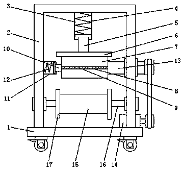
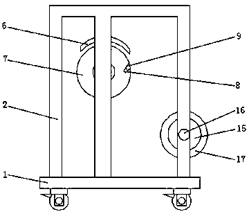
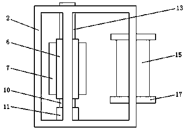

Image

  • Winding device for textile machine
  • Winding device for textile machine
  • Winding device for textile machine

Examples


Embodiment Construction

[0018] The present invention will be further described below in conjunction with specific embodiments, wherein, the accompanying drawings are only for exemplary illustrations, and what is shown is only a schematic diagram, rather than a physical map, and cannot be understood as a limitation to this patent. In order to better illustrate the present invention Specific embodiments, some parts in the drawings will be omitted, enlarged or reduced, and do not represent the size of the actual product. For those skilled in the art, it is understandable that some known structures and their descriptions in the drawings may be omitted. Based on The specific implementation modes in the present invention and all other specific implementation modes obtained by persons of ordinary skill in the art without making creative efforts all belong to the protection scope of the present invention.

[0019] see Figure 1-Figure 3 , the present invention provides a technical solution: a winding device ...


PUM


Abstract

The invention discloses a winding device for a textile machine. The winding device comprises a base. A supporting frame is vertically connected to the top of the base. The top of an inner cavity of the supporting frame is connected with a vertical sleeve pipe. A press-down spring is mounted in an inner cavity of the sleeve pipe. The bottom end of the press-down spring is connected with a telescopic rod, and the telescopic rod is connected to the bottom of the inner cavity of the sleeve pipe in a sliding manner and a sleeved manner. The bottom end of the telescopic rod is connected with a horizontal arc press plate. A winding barrel is connected to the bottom of the arc press plate in an attached manner. A horizontal inserting groove is formed in the surface of the winding barrel. A fixed strip is connected in the inserting groove in an inserted manner. The left end of the winding barrel is rotationally connected with an adjusting shaft. The winding device is simple in structure, stable, reliable, simple and convenient to operate and convenient to use, the winding barrel can be fast replaced, and the work efficiency is improved; cloth can be leveled in the winding process and is prevented from being wrinkled and folded, and the winding effect is improved; and the winding device can be suitable for winding work of cloth of different widths, adaptability is improved, and wide application prospects are achieved.

Description

technical field [0001] The invention relates to the technical field of textile machinery equipment, in particular to a winding device for textile machinery. Background technique [0002] After the textile machinery and equipment are finished spinning, the fabric needs to be rolled into rolls and divided into packages. The formation of each roll of fabric is usually wound by the winding device on the textile equipment, and the fabric is wound on it during the rotation of the roll. , when a reel is full of cloth, it needs to be replaced with a new reel, and after replacing the new reel, the cloth needs to be reattached to the surface of the reel, so that the winding of the cloth can be restarted. [0003] However, the existing winding device for textile machinery generally adopts the method of manually pasting the cloth head on the surface of the winding drum through adhesive tape, which is not fixed enough, and it is inconvenient to quickly replace the winding drum. During th...

Claims


Application Information

Patent Timeline
Patent Type & Authority Applications(China)
IPC IPC(8): B65H18/02B65H23/032B65H23/26B65H18/26B65H18/10B65H75/28
CPCB65H18/028B65H18/10B65H18/26B65H23/0322B65H23/26B65H75/28B65H2402/42B65H2701/174B65H2402/54
Inventor 施美雅
Owner 苏州闽国纺织科技有限公司
Why Eureka
Try Eureka