Pneumatic wind-proof rail clamping device

A technology of windproof clip and windproof cover, which is applied in the directions of travel mechanism, load hanging element, transportation and packaging, etc., can solve the problems of high requirements on the license of hydraulic components, unsuitable for long-distance transmission of power, and complex structure of hydraulic rail clamps. , to achieve good clamping effect, simple structure, and reduce the effect of wind

Pending Publication Date: 2018-06-22
台州中奥检测科技有限公司 +1
View PDF1 Cites 0 Cited by
  • Summary
  • Abstract
  • Description
  • Claims
  • Application Information

AI Technical Summary

Problems solved by technology

[0002] The crane rail clamp is mainly used to prevent the outdoor crane from sliding along the track under the action of strong wind. It usually uses a clamp connected with the bottom structure of the crane to clamp the two sides of the head of the track to brake the crane. Now Some rail clamps are generally divided into two types: manual and electric. Among them, the manual rail clamp is generally a screw type with a simple structure, but the clamping force is small and the action is slow. For small or temporary cranes, for large cranes or port cranes, electric rail clamps are mainly used. The existing electric rail clamps are complex in structure, and most of them are clamped by hydraulic pressure. For example, Chinese patent [application published No. CN105883611A] discloses an electro-hydraulic rail clamp, which includes a fixed frame, on which a connecting rod A and a connecting rod B are respectively hinged near the left end and the right end, and the connecting rod A and the connecting rod The lower end of B is respectively fixedly connected with clamp arm A and clamp arm B, and a steel rail is arranged between the clamp arm A and the clamp arm B, and the described steel rail is located below the fixed frame, and the clamp arm A and the clamp arm B is arranged symmetrically on both sides of the rail, and the top ends of the connecting rod A and the connecting rod B are respectively hinged with hinged rod A and hinged rod B, and the top ends of the hinged rod A and hinged rod B are connected with an electro-hydraulic telescopic rod
Although the hydraulic rail clamp can achieve a certain clamping effect, due to the complex structure of the hydraulic rail clamp, it is heavy, large in size, high in cost, poor in sealing performance, and the hydraulic oil is greatly affected by temperature. The viscosity will change with the change of temperature. It is not suitable for long-distance transmission of power, and some air mixed in it may easily cause crawling. Vibration and noise will seriously affect the working performance, and the hydraulic components require high precision and are difficult to assemble. Strict use and maintenance

Method used


Image

  • Pneumatic wind-proof rail clamping device
  • Pneumatic wind-proof rail clamping device
  • Pneumatic wind-proof rail clamping device

Examples


Embodiment 1

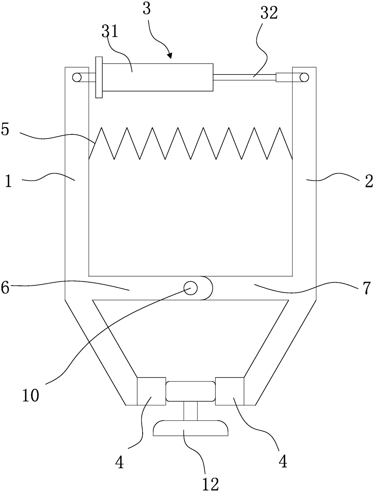
[0028] refer to figure 1 , the present embodiment is a pneumatic windproof rail clamp, which is characterized in that it includes a first clamp arm 1 and a second clamp arm 2 which are symmetrically arranged in pairs and can rotate with each other, the top end of the first clamp arm 1 and the There is a cylinder 3 between the top ends of the second clamp arm 2, the cylinder 3 includes a cylinder block 31 and a piston rod 32, the cylinder block 31 is connected to the first clamp arm 1, and the piston rod 32 is connected to the second clamp arm 2, the bottom end of the first clamp arm 1 and the bottom end of the second clamp arm 2 both have clamping parts 4, and a clamping spring is also arranged between the first clamp arm 1 and the second clamp arm 2 5. The middle part of the first clamp arm 1 has a hinged rod 1 extending toward the second clamping arm 2, and the middle part of the second clamping arm 2 has a hinged rod 2 extending toward the first clamping arm 1 side. 7. The...

Embodiment 2

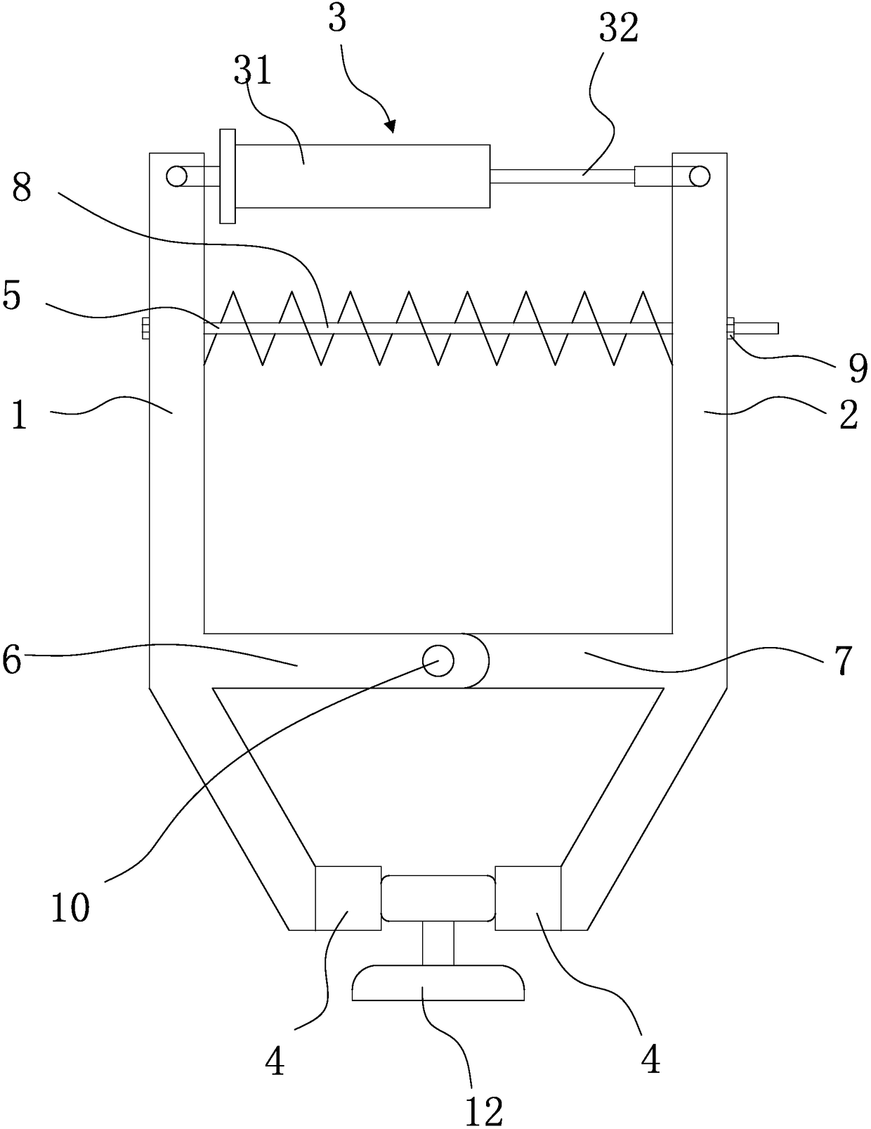
[0032] refer to figure 2 , the structure of the second embodiment is basically the same as that of the first embodiment, the difference is that a screw assembly is also provided between the first clamp arm 1 and the second clamp arm 2, and the screw assembly includes an adjusting screw 8 and an adjusting nut 9, The adjusting screw 8 is sequentially interspersed on the first clamp arm 1 and the second clamp arm 2, and the nut of the adjusting screw 8 abuts against the outer wall of the first clamp arm 1, and the adjusting nut 9 is threaded on the adjusting The end of the screw rod 8, and the adjustment nut 9 is against the outer wall of the second clamp arm 2, the clamping spring 5 is sleeved on the adjustment screw rod 8, and the clamping spring 5 and the adjustment screw rod 8 are coaxially arranged, and the adjustment More convenient, less adjustment resistance.

Embodiment 3

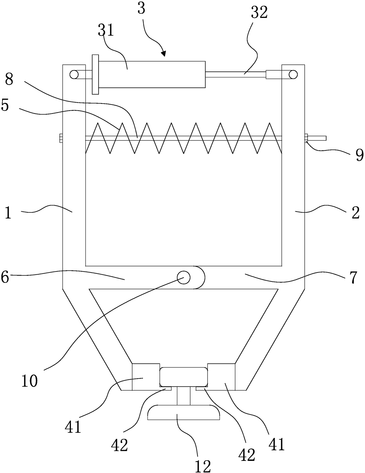
[0034] refer to image 3 , the structure of the third embodiment is basically the same as that of the second embodiment, the difference is that the clamping member 4 includes a vertical clamping portion 41 and a laterally disposed anti-off portion 42, and the anti-off portion 42 is connected to the clamping portion 41 bottom end. When the clamping part 4 clamps, the two clamping parts 41 are clamped on both sides of the upper layer of the I-steel track 12, and the anti-off part 42 is located between the upper and lower layers of the I-steel track 12. When the wind force is too large At this time, the top surface of the anti-falling part 42 can lean against the upper bottom surface of the I-beam rail 12, which not only avoids falling out, but also further increases the friction force, ensures stability, and avoids overturning.


PUM


Abstract

The invention provides a pneumatic wind-proof rail clamping device, and belongs to the technical field of lifting equipment. The problems that when an existing rail clamping device is used, stabilityand safety are poor are solved. The pneumatic wind-proof rail clamping device comprises a first clamp arm and a second clamp arm which are arranged in pair and can rotate, an air cylinder is arrangedbetween the top end of the first clamp arm and the top end of the second clamp arm, and comprises an air cylinder body and a piston rod, the air cylinder body is hinged to the first clamp arm, the piston rod is hinged to the second clamp arm, clamping parts are arranged at the bottom end of the first clamp arm and the bottom end of the second clamp arm, and a clamping spring is arranged between the first clamp arm and the second clamp arm. when the device is used, the clamping spring is in the compression state all the time, clamping parts on the two clamp arms are forced to abut against an I-shaped steel rail way to achieve clamping, when the rail clamping device needs to be opened, the air cylinder overcomes spring force of the clamping spring, the rail clamping device is opened, the structure is simple, and stability is good.

Description

technical field [0001] The invention belongs to the technical field of lifting equipment, in particular to a rail clamp, in particular to a pneumatic windproof rail clamp. Background technique [0002] The crane rail clamp is mainly used to prevent the outdoor crane from sliding along the track under the action of strong wind. It usually uses a clamp connected with the bottom structure of the crane to clamp the two sides of the head of the track to brake the crane. Now Some rail clamps are generally divided into two types: manual and electric. Among them, the manual rail clamp is generally a screw type with a simple structure, but the clamping force is small and the action is slow. For small or temporary cranes, for large cranes or port cranes, electric rail clamps are mainly used. The existing electric rail clamps are complex in structure, and most of them are clamped by hydraulic pressure. For example, Chinese patent [application published No. CN105883611A] discloses an e...

Claims


Application Information

Patent Timeline
Patent Type & Authority Applications(China)
IPC IPC(8): B66C9/18B66C15/00
CPCB66C9/18B66C15/00
Inventor 林汝明金仲平李隆骏陈仁毅王涤宇张雍吕信策陈永玉
Owner 台州中奥检测科技有限公司
Why Eureka
Try Eureka