Bridge crane anti-swing control method based on neural network PID

A bridge crane and neural network technology, applied in the field of anti-sway positioning control system of bridge crane, can solve the problems of increased wear on the side of the track, offset of the center of gravity of the vehicle, and complex operating environment of the crane, and achieve the goal of eliminating swing and precise positioning Effect

Active Publication Date: 2018-06-22
HARBIN INST OF TECH AT WEIHAI
View PDF6 Cites 8 Cited by
  • Summary
  • Abstract
  • Description
  • Claims
  • Application Information

AI Technical Summary

Problems solved by technology

Mechanical anti-swing is to use mechanical means to consume the swinging energy of the hanging object to finally eliminate the swing. This kind of anti-swing device usually has a very complicated structure, poor reliability, troublesome maintenance, and the anti-swing effect is not good; electronic anti-swing Divided into open-loop and closed-loop
The cost of the open-loop anti-sway system is low, but because the operating environment of the crane is very complicated, many unconsidered factors will interfere with the actual operation, and the reliability cannot be guaranteed
At the same time, the open-loop method is difficult to consider the problem of precise positioning
The traditional closed-loop control uses PID control to adjust the swing angle of the hanging object, but its sensitivity is low and its adaptability is poor.
[0004] Another problem that often occurs during the operation of bridge cranes is the phenomenon of "gnawing rails". During the operation of the crane, there are many factors that will cause the speed of the motor of the crane to be unequal, such as changes in wheel friction, mechanical interference, and shifting of the center of gravity of the vehicle. , mutation of unilateral load, etc.
The occurrence of rail gnawing leads to increased running resistance, increased wear on the side of the track, and a sharp decrease in wheel life, etc.

Method used


Image

  • Bridge crane anti-swing control method based on neural network PID
  • Bridge crane anti-swing control method based on neural network PID
  • Bridge crane anti-swing control method based on neural network PID

Examples


Embodiment Construction

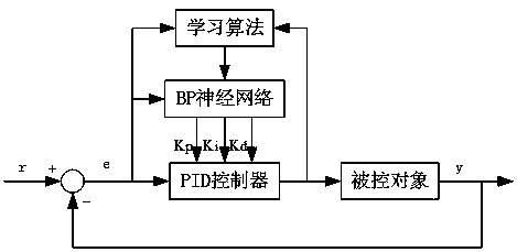
[0050] In order to make the technical solution and advantages of the present invention clearer, the technical solution will be clearly and completely described below in conjunction with the accompanying drawings of the present invention. The invention combines the BP neural network with the traditional PID control, utilizes the powerful approximation ability of the neural network, can adjust the PID parameters online and in real time through learning, so that the controller can adapt to the structural parameters of the controlled object and the change of the environment.

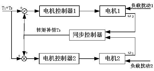
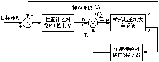
[0051] Such as Figure 1-Figure 4 The shown bridge crane anti-sway control method based on neural network PID is characterized in that comprising the steps:

[0052] Step 1. The target speed curve of the overhead crane cart is given, and the overhead crane cart moves according to the given target speed curve; the motor controller controller simulates the ideal driving process of the driver according to the t...


PUM


Abstract

The invention discloses a bridge crane anti-swing control method based on a neural network PID, and relates to the field of bridge cranes. A BP neural network is combined with a traditional PID controller, the neural network is adopted as an on-line estimator, and an optimal PID control parameter is given in real time. An angle neural network PID controller and a position neural network PID controller are designed, and the swing angle and position of an objected lifted by a crane are controlled. Meanwhile, in order to solve the problem that motors on the two sides are unbalanced in rotation speed due to load disturbance in the operation process of a crane cart, a motor rotation speed synchronous controller is designed and used for torque compensation. Through the bridge crane anti-swing control method, the crane can be precisely positioned, lifted object swing can be eliminated, and in addition, the rail gnawing phenomenon caused by the unequal rotation speeds of the two motors of thecart in the crane transport process can be avoided.

Description

technical field [0001] The invention relates to the field of bridge cranes, in particular to a designed bridge crane anti-sway positioning control system which also has the function of anti-gnawing rails. Background technique [0002] As an indispensable means of transportation, bridge cranes have been widely used in workshops, ports and other places. However, during the loading, unloading and transportation of cranes, due to the acceleration and deceleration of carts and trolleys and the influence of external interference factors, the load will swing back and forth, which not only affects production efficiency but also poses certain safety hazards. Moreover, with the improvement of automation and mechanization, the continuous expansion of production scale, and the increasing production efficiency, cranes are used more and more widely in the modern production and transportation process, and their role is becoming more and more important. Therefore, the safety and efficiency ...

Claims


Application Information

Patent Timeline
IPC IPC(8): B66C13/48B66C13/06
CPCB66C13/063B66C13/48
Inventor 王大方魏辉徐泽绪汪井威汤志皓蔡金逸
Owner HARBIN INST OF TECH AT WEIHAI
Why Eureka
Try Eureka