Color plate reverse ceiling upper-air sliding device and reverse ceiling construction method

A sliding device and anti-ceiling technology, which is applied in the direction of hoisting device, winch device, building structure, etc., can solve the problems that the stability of scaffolding cannot be guaranteed, and the safety of construction personnel cannot be guaranteed, and the cost of labor and machine tools can be reduced. Reduced, high practical value, increased protection effect

Pending Publication Date: 2018-06-22
黑龙江省建筑安装集团有限公司
View PDF0 Cites 3 Cited by
  • Summary
  • Abstract
  • Description
  • Claims
  • Application Information

AI Technical Summary

Problems solved by technology

The height of the erection should not be too high, generally within 18m. If the erection is too high, the stab

Method used


Image

  • Color plate reverse ceiling upper-air sliding device and reverse ceiling construction method
  • Color plate reverse ceiling upper-air sliding device and reverse ceiling construction method
  • Color plate reverse ceiling upper-air sliding device and reverse ceiling construction method

Examples


Embodiment 1

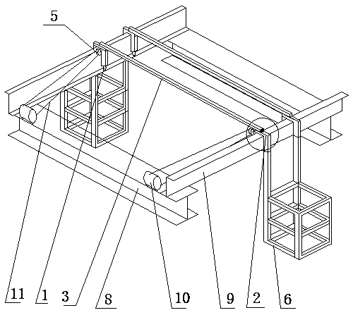
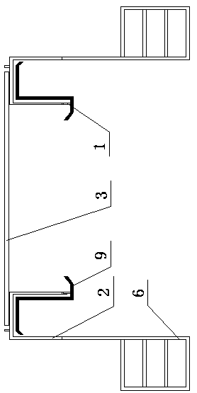
[0034] A color steel plate anti-ceiling high-altitude sliding device, which consists of: two hanging baskets 6, the hanging baskets are connected to the roller 1 through a U-shaped connecting device 2, and the two hanging baskets are connected by a U-shaped connecting device , the bolt 4 and the connecting square steel 3 are connected together, the outer end of the U-shaped connecting device has a protective sleeve, and the side of the U-shaped connecting device has a fixed pulley block A5, and the described U-shaped connecting device is placed on the Z-shaped On the purlin 9, the two ends of the Z-shaped purlin are welded on the I-beam 8.

Embodiment 2

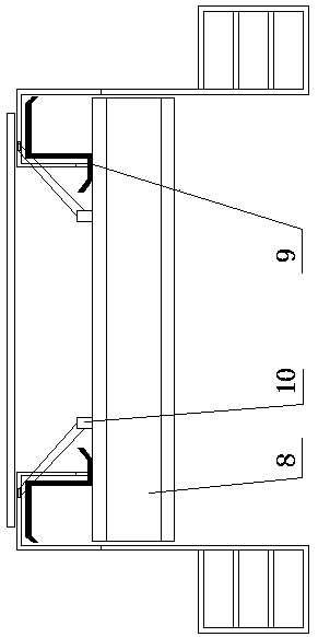
[0036] In the high-altitude sliding device of the color steel plate anti-ceiling described in Example 1, a set of fixed sliding wheels B10 is welded on the side of the I-beam, and the fixed sliding wheels B and the fixed sliding wheels A pass through the traction rope 11 Connection, the U-shaped connection device and the connection square steel are connected by the bolts, and the surface of the hanging basket fixing device is fixedly installed with a rubber wear-resistant layer.

Embodiment 3

[0038] A construction method using the color steel plate anti-ceiling high-altitude sliding device described in Example 1-2. This method is to first use BIM to arrange the roof color plates, and then measure the setting out on site according to the construction drawings to obtain accurate values. The measured value is provided to the color plate manufacturer, and the processing plant reviews and processes the color plate according to the on-site measurement defense line. After the color plate is transported to the site, the supervisor will inspect and accept it on site, and provide the product qualification certificate, quality inspection report, etc. After the completion, use the truck crane to hoist the color plate to the Z-shaped purlin and fix it with a rope;

[0039] Then hang the hanging basket on the Z-shaped purlin and install the lifeline, install a temporary sliding device on the steel beam, and connect the hanging basket and the temporary sliding device with a wire ...


PUM


Abstract

The invention provides a color plate reverse ceiling upper-air sliding device and a reverse ceiling construction method. As for a traditional roof color plate inner plate, mounting work procedures arecomplex, needed environment factors are many, and consumption in the aspects of manpower, funds and machines is over large. The color plate reverse ceiling upper-air sliding device comprises two hanging baskets (6), the hanging baskets are connected with idler wheels (1) through U-shaped connecting devices (2), and the two hanging baskets are connected together through the U-shaped connecting devices, bolts (4) and connecting square steel (3). The outer ends of the U-shaped connecting devices are provided with protecting sleeves, the side edges of the U-shaped connecting devices are providedwith fixed pulley sets A (5), and the U-shaped connecting devices are placed on Z-shaped purlines (9). The two ends of the Z-shaped purlines are welded to I-shaped steel (8). The invention discloses the color plate reverse ceiling sliding device and a using method.

Description

Technical field: [0001] The invention belongs to the technical field of construction equipment, and relates to a high-altitude sliding device for an anti-suspension ceiling of a color steel plate and a construction method for an anti-suspension ceiling. Background technique: [0002] Due to the complex installation process of the inner panel of the traditional roof color board, mobile scaffolding needs to be erected, and the ground conditions must have good flatness, so as to ensure the construction of the inner panel, but the construction of mobile scaffolding requires a relatively large investment in manpower, materials, and machines, and the cost is relatively high. High, and the flexibility is very poor, the risk is very high when moving, the construction personnel do not have a good place to tie the safety rope, and the safety of the construction personnel cannot be guaranteed; [0003] Traditional approaches have limitations. The height of erection should not be too h...

Claims


Application Information

Patent Timeline
IPC IPC(8): B66F19/00E04G21/16
CPCE04G21/162E04G21/167B66F19/00
Inventor 丛占军刘斌刘松于春艳刘起超高知州王飒张煦东宋明旭武瑞琪尹志慧
Owner 黑龙江省建筑安装集团有限公司
Why Eureka
Try Eureka