Lifting rotary type vehicle parking device for household

A technology of lifting and rotating vehicles, which is applied in the direction of buildings, building types, and buildings where cars are parked. It can solve problems such as poor flexibility and large safety hazards, and achieve the effects of easy operation, strong adaptability, and convenient car retrieval.

Inactive Publication Date: 2018-06-22
CHONGQING UNIV
View PDF6 Cites 3 Cited by
  • Summary
  • Abstract
  • Description
  • Claims
  • Application Information

AI Technical Summary

Problems solved by technology

In the prior art, there are devices such as lifting and moving, vertical / horizontal circulation, vertical lifting and simple lifting, but they all have disadvantages such as poor flexibility and great safety hazards.

Method used


Image

  • Lifting rotary type vehicle parking device for household
  • Lifting rotary type vehicle parking device for household
  • Lifting rotary type vehicle parking device for household

Examples


Embodiment 1

[0042] This embodiment discloses a lifting and rotating vehicle parking device for household use, which has the advantages of convenience and flexibility, strong applicability, and high space utilization rate.

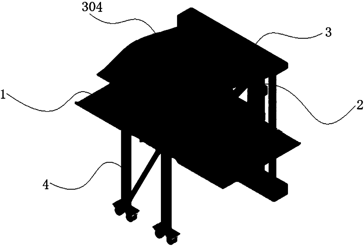
[0043] see figure 1 with Figure 10 , The lifting and rotating vehicle parking device for household use includes: a vehicle loading plate 1, a lifting and rotating column 2, a fixed frame 3, an auxiliary lifting device 4 and a PLC controller 5.

[0044] see Figure 11 , the fixed frame 3 includes guide rails 301 , sunshade brackets 302 and legs 303 . The guide rail 301 and the sunshade support 302 are arranged horizontally, and the supporting legs 303 are arranged vertically. One end of the guide rail 301 and the sunshade bracket 302 is connected to each other through a leg 303 . The guide rail 301, the sunshade bracket 302 and the legs 303 together form a C-shaped structure. The guide rail 301 is fixed on the ground. The guide rail 301 is a U-shaped guide rail, ...

Embodiment 2

[0051] This embodiment discloses a lifting and rotating vehicle parking device for household use, including: a vehicle loading plate 1 , a lifting and rotating column 2 , a fixed frame 3 , an auxiliary lifting device 4 and a PLC controller 5 .

[0052] The fixed frame 3 includes guide rails 301 , sunshade brackets 302 and legs 303 . The guide rail 301 and the sunshade support 302 are arranged horizontally, and the supporting legs 303 are arranged vertically. One end of the guide rail 301 and the sunshade bracket 302 is connected to each other through a leg 303 . The guide rail 301, the sunshade bracket 302 and the legs 303 together form a C-shaped structure. The guide rail 301 is fixed on the ground. The guide rail 301 is a U-shaped guide rail, and the U-shaped opening faces upward. A rack 3011 is arranged in the U-shaped groove on the guide rail 301 to provide track support for the translation of the lifting and rotating column 2 . A plastic shed 304 is fixedly arranged o...


PUM


Abstract

The invention provides a lifting rotary type vehicle parking device for household. The lifting rotary type vehicle parking device comprises a vehicle carrying plate, a lifting rotary column, a fixingframe, an auxiliary lifting device and a PLC. In the working process, the PLC is started up by pressing a button or through wireless remote control. The PLC controls to start up a transverse moving motor, and the transverse moving motor drives a gear to rotate to drive a moving box, the lifting rotary column and the vehicle carrying plate to move along a guide rail. A rotary motor is started, anda transmission device rotates to drive the lifting rotary column and the vehicle carrying plate to rotate a designated angle. A lifting motor I and a lifting motor II are started, the lifting motor Idrives a chain wheel to rotate by lifting the transmission device up and down, the vehicle carrying plate descends by lifting a chain up and down, and the lifting motor II drives a lifting screw rod through a commutator to assist the vehicle carrying plate to descend. After the vehicle carrying plate descends to the ground, a vehicle owner drives the vehicle on or off the vehicle carrying plate. The device is high in adaptability, and can be used for a variety of parking modes such as transverse side by side, longitudinal side by side or inclining side by side. The mechanical device is free and flexible, and a control system is convenient to operate.

Description

technical field [0001] The invention relates to the technical field of parking equipment, in particular to a lifting and rotating vehicle parking device. Background technique [0002] At present, most of the cities in China are very expensive, and the traffic pressure is gradually changing from dynamic to static. "Parking difficulty" has long become a public problem restricting urban development. The traffic violations such as parking on the road caused by this have encroached on public space and affected the normal life order of residents. [0003] Since 2005, the number of cars in my country has increased by more than 15% every year, and the rapid growth rate of car ownership continues to challenge the limit of the basic traffic carrying capacity. According to estimates, the current average ratio of cars to parking spaces in large cities in my country is about 1:0.8, and in small and medium-sized cities is about 1:0.5, with a parking space gap of more than 50 million. Th...

Claims


Application Information

Patent Timeline
Patent Type & Authority Applications(China)
IPC IPC(8): E04H6/06E04H6/28
CPCE04H6/06E04H6/282
Inventor 李继秀侯德尚丁宏韩嘉童王钰晴宁先雄肖贵坚
Owner CHONGQING UNIV
Why Eureka
Try Eureka