
Water-turbine generator set guide vane water leakage detecting method and system

A technology for generating sets and detection methods, which is applied to hydroelectric power generation, engine components, machines/engines, etc., and can solve problems such as errors and inaccuracies

Active Publication Date: 2018-06-22
湖南省湘电试验研究院有限公司
View PDF3 Cites 8 Cited by
  • Summary
  • Abstract
  • Description
  • Claims
  • Application Information

AI Technical Summary

Problems solved by technology

Therefore, the selection of the calculation period itself will produce a certain error in the calculation of the leakage; at the same time, the H(t) curve t=0 moment fitted by the randomly selected calculation period is used as the closing time of the inlet gate or vent hole, which calculates The flow Q of the current water head H is the leakage of the guide vane, which is also inaccurate

Method used


Image

  • Water-turbine generator set guide vane water leakage detecting method and system
  • Water-turbine generator set guide vane water leakage detecting method and system
  • Water-turbine generator set guide vane water leakage detecting method and system

Examples


Embodiment 1

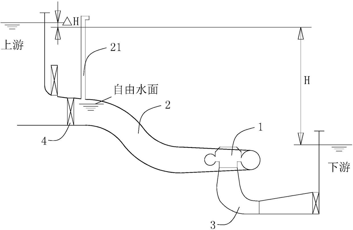
[0022] The following will be figure 1 The hydro-generator set shown is taken as an example, and the method and system for detecting water leakage of the guide vane of the hydro-generator set according to the present invention will be further described in detail. see figure 1 , the guide vane 1 of the hydroelectric generator set is installed between the inlet pipe 2 and the tail water section 3, the front end of the water inlet pipe 2 communicates with the upstream through the fast gate 4, the tail water section 3 communicates with the downstream, and the water inlet pipe 2 is free Ventilation holes 21 are provided on the upper side of the water surface to communicate with the outside world, where H represents the water level difference between the upstream and downstream, and ΔH represents the change in water head caused by the opening and closing of the water inlet pipe 2 . The flow path leveling device is installed at 2 places of the water inlet pipe. The function of the fl...

Embodiment 2

[0037] In this embodiment, on the basis of Embodiment 1, in step 3), a step including calculating the water leakage of the guide vane under the rated water head according to formula (2) is further added;

[0038] Q r =Q 0 (H r / H 0 ) 0.5 (2)

[0039] In formula (2), Q r is the water leakage of the guide vane under the rated water head, H r is the rated water head, H 0 is the time point t when the flow channel leveling device is closed 0 The pressure head before and after the guide vane.

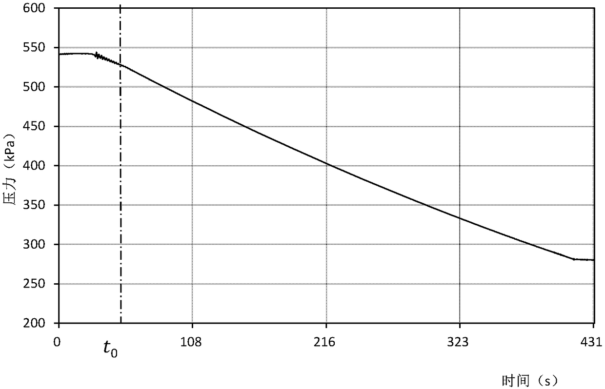
[0040] In this embodiment, when testing, the upstream water level is 248.75m, the downstream water level is 190.55m, and the pressure difference from the center of the water inlet gate to the upstream water level is 32m; t 0 The water level of the vent hole at all times is 246.629m, and the pressure difference between the center of the inlet gate and the water level of the vent hole is 29.88m, then t 0 The water leakage of the gate at all times is 3.37% of the water leakage of the ...


PUM


Abstract

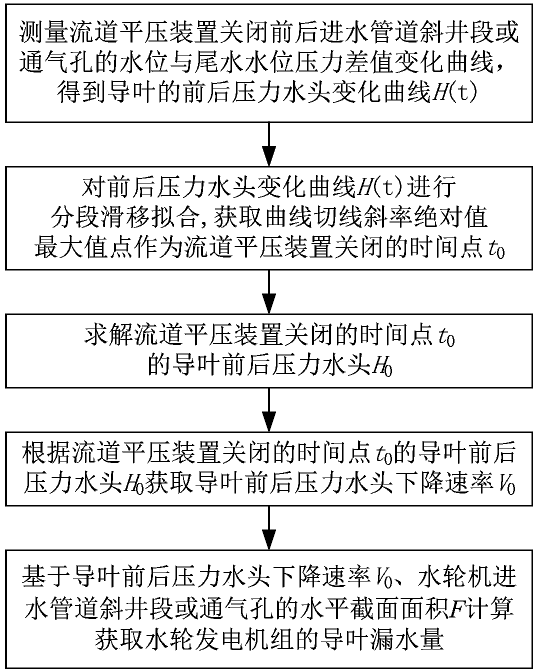
The invention discloses a water-turbine generator set guide vane water leakage detecting method and system. The water-turbine generator set guide vane water leakage detecting method comprises the following steps: measuring a variation curve of the pressure difference between the water level of an inclined shaft segment or an air vent of a water inlet pipeline and the tailwater level before and after a flow channel flat-pressing device is shut down, so as to obtain a variation curve of the guide vane before-and-after pressure head; based on a secondary least square fitting model, carrying out segmented slip fitting, acquiring the maximum point of an absolute value of the curve tangent slope as a time point for the shut-down of the flow channel flat-pressing device, acquiring the guide vanebefore-and-after pressure head at the time point for the shut-down of the flow channel flat-pressing device through a solution, and acquiring the guide vane before-and-after pressure head reduction rate; and based on the guide vane before-and-after pressure head reduction rate and the horizontal section area of the inclined shaft segment or the air vent of the water-turbine water inlet pipeline, calculating the water-turbine generator set guide vane water leakage. By adoption of the water-turbine generator set guide vane water leakage detecting method and system disclosed by the invention, thetransient process of water pressure fluctuations caused by the shut-down of the flow channel flat-pressing device can be filtered out; the interference of the gate water leakage in the calculation ofthe guide vane water leakage can be fundamentally eliminated; and the advantages that the detecting result is correct and the testing operation is rapid can be achieved.

Description

technical field [0001] The invention relates to the on-site testing technology of a hydropower station, in particular to a method and system for detecting water leakage of a guide vane of a hydroelectric generating set, which are used for on-site detection and diagnosis of the water leakage of a guide vane of a hydroelectric generating set. Background technique [0002] With the continuous increase of hydropower installed capacity in my country, the economic benefits and safety evaluation of hydropower units are also more stringent. The water leakage of the movable guide vanes of hydropower units is too large. On the one hand, water resources cannot be fully utilized, which is not conducive to the economic operation of power plants. , on the other hand, it will cause difficulty in shutting down the unit or creep in shutting down, threatening the safe operation of the power plant. Therefore, it is very necessary to measure the water leakage of the guide vane before and after t...

Claims


Application Information

Patent Timeline
IPC IPC(8): F03B11/00
CPCF03B11/008Y02E10/20
Inventor 毕智伟黄波蒋金娥张军肖剑
Owner 湖南省湘电试验研究院有限公司
Learn More