
Test device for exerting different constraints on soil unit

A technology of testing device and loading device, applied in the direction of using stable shear force to test material strength, using stable tension/pressure to test material strength, measuring device, etc., can solve the error of test results, without considering the soil sample side To solve problems such as deformation, to achieve the effect of real measurement data and simple device structure

Pending Publication Date: 2018-06-22
CHANGAN UNIV +1
View PDF0 Cites 8 Cited by
  • Summary
  • Abstract
  • Description
  • Claims
  • Application Information

AI Technical Summary

Problems solved by technology

The conventional method of indoor compression test is to place the soil sample in the ring knife and place it in a rigid container to apply vertical load, so that the soil sample is subjected to compression test under the condition of complete rigid confinement, and the soil sample is not considered in the test process. Lateral deformation, which is inconsistent with the force and deformation conditions of the soil material around which the soil element is flexible in actual engineering
At present, the test device for shearing in geotechnical tests is a circular standard shearing box, and the shearing area gradually decreases with the shearing, and there are errors in the test results.

Method used


Image

  • Test device for exerting different constraints on soil unit
  • Test device for exerting different constraints on soil unit
  • Test device for exerting different constraints on soil unit

Examples


Embodiment Construction

[0023] The present invention is described in further detail below in conjunction with accompanying drawing:

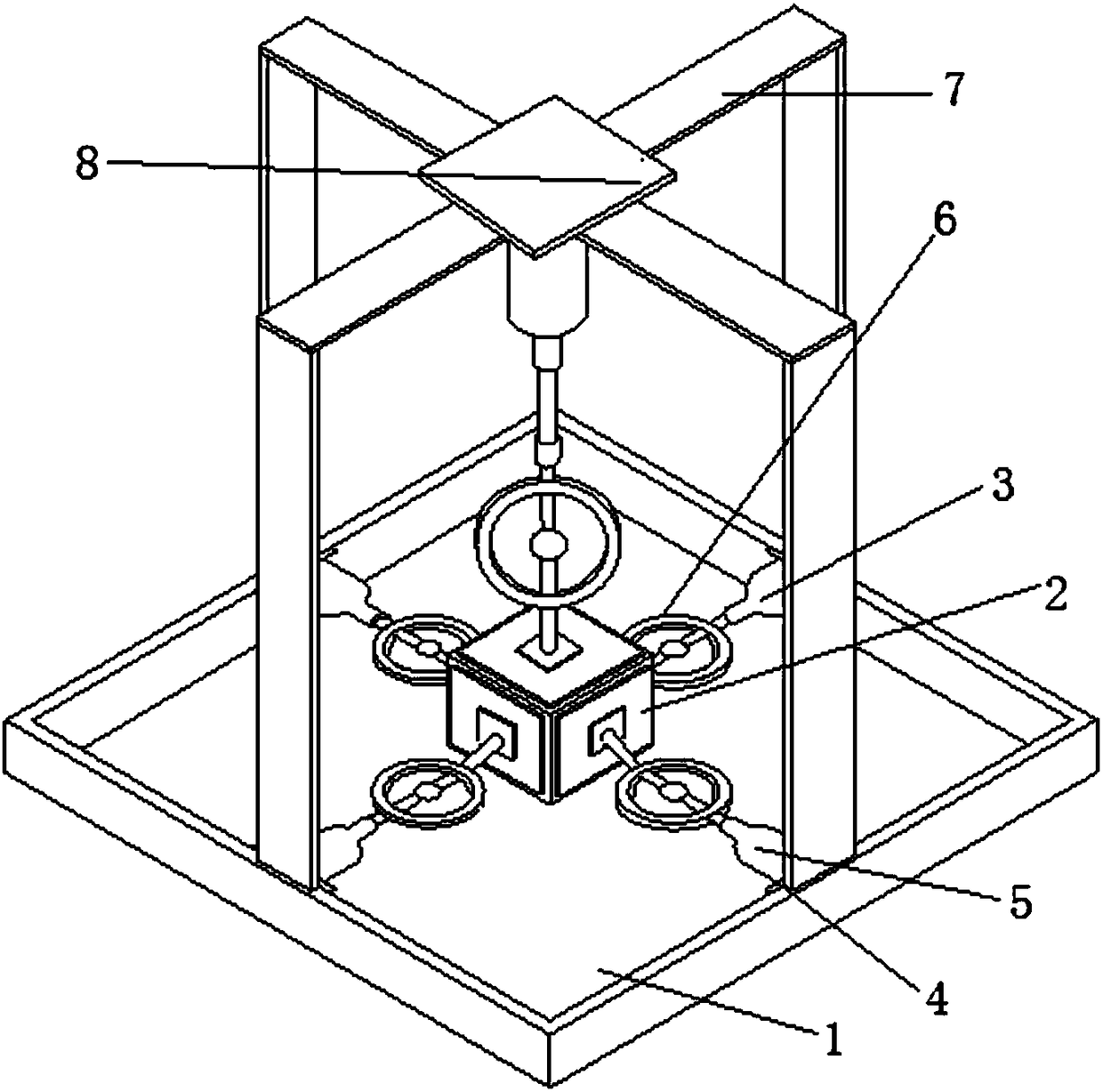
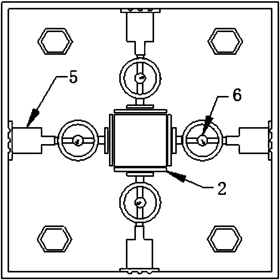
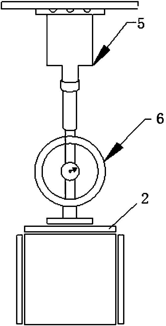
[0024] Such as Figure 1 to Figure 6 As shown, a soil unit test piece testing device includes a soil sample clamping device, a loading device 3 and a sliding device 4;

[0025] Wherein the soil sample clamping device includes a soil sample placing platform 1 and a pressure plate 2, the soil sample placing platform 1 is provided with a groove for positioning and placing the soil sample specimen, and the pressure applying plate 2 includes an upper pressure plate and a side pressure plate, and the side pressure plate The outside of the soil sample to be tested is evenly arranged in the groove of the soil sample placing platform, the outside of the side pressure plate and the upper end of the upper pressure plate are connected to the loading device 3, and the sliding device 4 is arranged outside the loading device 3 for fixed or mobile loading device;

[0026] Specifical...


PUM


Abstract

The invention discloses a test device of a soil unit test piece. A side press plate is uniformly arranged on the outer side of a soil sample test piece to be tested arranged in a soil sample holding table groove; meanwhile, a sliding device capable of sliding and being fixed is arranged at the outer side of a loading device; the loading device is used for exerting a load on the top surface of thesoil unit test piece, and simultaneously performs different constraints on the opposite side, third side and fourth side of the soil unit test piece; the constraints at the identical sampling positionare exerted on the test soil unit test pieces according to the constraint conditions received by the soil unit in the roadbed sampling position; the test on force in different directions of the soilsample test piece to be tested can be realized, so that the soil sample test piece to be tested is naturally stressed. The device has the advantages that the structure is simple; the soil unit test piece can be subjected to direct shearing test under the constraint conditions; in addition, the shearing surface of the soil unit test piece is enabled to be always in contact with the soil body in thesharing process; the Poisson's ratio of the soil sample is measured through measuring the peripheral deformation and vertical deformation of the soil unit test piece; the measuring authenticity of the soil unit test piece is effectively improved.

Description

technical field [0001] The invention belongs to the field of geotechnical engineering, and relates to a soil unit test piece testing device. Background technique [0002] Indoor compression test and shear test are common tests in geotechnical tests to determine the deformation and strength of soil samples, and are used to analyze the settlement of building foundations and roadbeds and determine the parameters of stability. The conventional method of indoor compression test is to place the soil sample in the ring knife and place it in a rigid container to apply vertical load, so that the soil sample is subjected to compression test under the condition of complete rigid confinement, and the soil sample is not considered in the test process. Lateral deformation, which is inconsistent with the force and deformation conditions of the flexible soil material around the soil unit in actual engineering. At present, the shearing test device in the geotechnical test is a circular stan...

Claims


Application Information

Patent Timeline
IPC IPC(8): G01N3/08G01N3/24G01N3/02
CPCG01N3/02G01N3/08G01N3/24G01N2203/0025G01N2203/0019
Inventor 李哲张娟朱金环李文曹升亮王中将郭胜男刘阳王聚军代保森
Owner CHANGAN UNIV
Learn More