
A multi-frequency antenna device

A multi-frequency antenna, low-frequency technology, applied in the directions of antenna coupling, antenna grounding switch structure connection, radiating element structure form, etc., can solve the problems of antenna performance degradation, commercial competitiveness reduction, complex antenna structure, etc., and achieve good frequency band isolation characteristics Effect

Active Publication Date: 2020-03-27
永州天勤电子科技有限公司
View PDF7 Cites 0 Cited by
  • Summary
  • Abstract
  • Description
  • Claims
  • Application Information

AI Technical Summary

Problems solved by technology

However, the antennas of the above-mentioned known technologies have many disadvantages
[0003] For example, the structure of the planar inverted-F antenna is relatively complicated, and because the planar inverted-F antenna is a three-dimensional antenna, the additional mold cost and assembly cost lead to high cost, and the commercial cost is too high, and its commercial competitiveness will decrease. will reduce
The three-dimensional antenna is too large to be placed in the increasingly smaller mobile devices. If the three-dimensional antenna is forcibly reduced in size to achieve miniaturization, it will easily lead to a decline in antenna performance.
Especially in the field of multi-frequency antennas, the small size often causes coupling interference between frequency bands. How to take into account miniaturization while ensuring interference between different frequency bands has always been a difficult problem for people.
[0004] Therefore, how to propose a multi-frequency antenna, which can effectively improve the problems of complex structure, high cost, and poor isolation performance of conventional antennas, has become urgent.

Method used


Image

  • A multi-frequency antenna device
  • A multi-frequency antenna device
  • A multi-frequency antenna device

Examples


Embodiment Construction

[0022] Embodiments of the present invention are described below through specific examples, and those skilled in the art can easily understand other advantages and effects of the present invention from the content disclosed in this specification. The present invention can also be implemented or applied through other different specific embodiments, and various modifications or changes can be made to the details in this specification based on different viewpoints and applications without departing from the spirit of the present invention.

[0023] It should be noted that the diagrams provided in this embodiment are only schematically illustrating the basic idea of ​​the present invention, so only the components related to the present invention are shown in the drawings rather than the number, shape and Dimensional drawing, the type, quantity and proportion of each component can be changed arbitrarily during actual implementation, and the component layout type may also be more comp...


PUM


Abstract

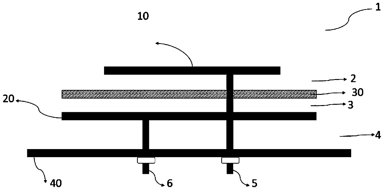
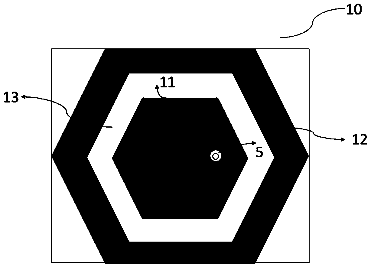
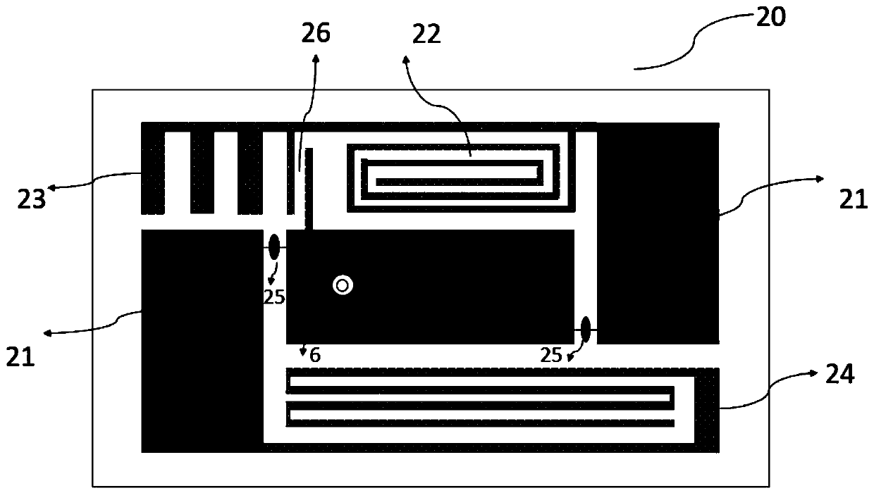
The invention provides a multi-frequency antenna device comprising a first metal layer, a second metal layer, a ground layer, and dielectric substrates positioned between the metal layers and betweenthe metal layer and the ground layer, wherein a metamaterial layer is arranged between the first metal layer and the second metal layer. According to the multi-frequency antenna device, the problem ofcontradiction among high gain, small interference and small size, which is difficult to overcome, in a traditional stacked antenna preparation method is solved, the extremely good frequency band isolation property is achieved via flexible and ingenious arrangement of the antenna wiring and the coupled isolation unit; the metamaterial unit is arranged between the two antenna metal layers, so thatthe antenna size is further reduced and the isolation between high frequency and low frequency is enhanced via the special conduction property of the metamaterial.

Description

technical field [0001] The invention belongs to the field of communication antennas, and more specifically relates to a multi-frequency antenna device for smart equipment. Background technique [0002] With the rapid development of wireless communication, antennas play a more important role in wireless communication smart device products. Today, as mobile devices have become an indispensable item in people's lives, it has also led to the vigorous development of the communication industry. Because of this, various small antennas have been developed and widely used in various For mobile devices, for example, planar inverted-F antennas, monopole antennas, stereo antennas, etc. However, the above-mentioned antennas of the known art have many disadvantages. [0003] For example, the structure of the planar inverted-F antenna is relatively complicated, and because the planar inverted-F antenna is a three-dimensional antenna, the additional mold cost and assembly cost lead to hig...

Claims


Application Information

Patent Timeline
Patent Type & Authority Patents(China)
IPC IPC(8): H01Q1/36H01Q1/38H01Q1/50H01Q1/52
CPCH01Q1/36H01Q1/38H01Q1/50H01Q1/52
Inventor 曹志翔
Owner 永州天勤电子科技有限公司
Learn More