Semi direct drive permanent magnet motor

A permanent magnet motor, semi-direct drive technology, applied in the direction of magnetic circuits, electromechanical devices, electrical components, etc., can solve the problems of frequent replacement, belt wear, heavy maintenance workload, etc., and achieve cost saving, land occupation, and structure simple and reliable effect

Pending Publication Date: 2018-06-22
大连宝锋机器制造有限公司
View PDF0 Cites 6 Cited by
  • Summary
  • Abstract
  • Description
  • Claims
  • Application Information

AI Technical Summary

Problems solved by technology

[0003] (1), the drive volume is large;
[0004] (2) The belt is severely worn, frequently replaced, and the maintenance workload is heavy;
[0005] (3) It is difficult to adjust the tightness of the belt, and the transmission efficiency is unstable and generally low;
[0006] (4) The load rate changes greatly during the operation of the pumping unit, and the power factor and efficiency of the asynchronous motor are relatively low under the condition of large load rate fluctuations

Method used


Image

  • Semi direct drive permanent magnet motor
  • Semi direct drive permanent magnet motor

Examples


Embodiment Construction

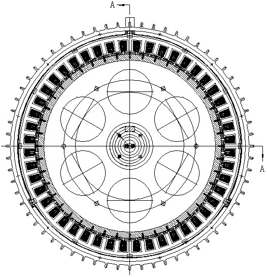
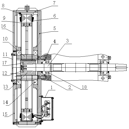
[0023] The structure of the semi-direct drive permanent magnet motor of the present invention is as follows: figure 1 As shown, the low-speed semi-direct drive permanent magnet motor is used to directly drive the reducer to run, and the original asynchronous motor, pulley and belt are cancelled. At the same time, according to its actual use, the motor structure is optimized. The main components of the semi-direct drive permanent magnet motor include: adjusting gasket 4, connecting end cover 5, motor stator 8, bushing 13, bushing baffle 12, motor rotor 10, Bearing 14 and end plate 15.

[0024] The specific structure is as follows: a motor stator 8 is installed on the inside of the motor housing 7, and a motor winding 6 is arranged on the motor stator 8. One end of the motor stator 8 is positioned on the connecting end cover 5 through a seam and fixed by screws, and the connecting end cover 5 is fixed by screws. Fixed on the reducer housing 2, the other end of the motor stator ...


PUM


Abstract

The invention provides a semi direct drive permanent magnet motor. A motor stator is mounted on the inner side of a motor housing. The motor stator is provided with a motor winding. A reducer input shaft penetrates through a reducer housing and a connection end cap and is mounted in the motor housing. The connection end cap is fixed on the reducer housing. The reducer input shaft is connected witha motor rotor through a shaft sleeve. The shaft sleeve end part is fixed on the reducer input shaft through a shaft sleeve barrier board. According to the invention, the semi direct drive permanent magnet is adopted for replacing a prior asynchronous motor and belt for driving. The invention has advantages that (1) the drive part is reduced in space occupancy; (2) a belt wheel is saved and belt maintenance and change are saved and influence on conveying efficiency due to belt pre-tightening force can be avoided; (3) influence on energy efficiency of the permanent motor due to load rate is almost none and the motor keeps high energy efficiency operation all the time, so that an energy conservation effect is distinct; (4) a reducer is used for fixing the motor stator and is connected with arotor coaxially, so that a simple and reliable structure is realized and a low cost is achieved.

Description

technical field [0001] The invention relates to the technical field of pumping units, in particular to the driving technology of the reducer of the pumping unit. Background technique [0002] The pumping unit is a kind of machine equipment for oil extraction. The existing structure of the pumping unit is usually to hang a large-diameter pulley on the input shaft of the reducer, and it is driven by an asynchronous motor through a belt. This driving structure has the following disadvantages: [0003] (1), the drive volume is large; [0004] (2) The belt is severely worn, frequently replaced, and the maintenance workload is heavy; [0005] (3) It is difficult to adjust the tightness of the belt, and the transmission efficiency is unstable and generally low; [0006] (4) The load rate changes greatly during the operation of the pumping unit, and the power factor and efficiency of the asynchronous motor are relatively low under the condition of large load rate fluctuations. C...

Claims


Application Information

Patent Timeline
Patent Type & Authority Applications(China)
IPC IPC(8): H02K1/16H02K1/27H02K5/16H02K7/08H02K15/02
CPCH02K1/16H02K1/2706H02K5/16H02K7/08H02K15/02
Inventor 贾先义
Owner 大连宝锋机器制造有限公司
Why Eureka
Try Eureka