
Coaxial two-terminal output integrated permanent magnet transmission device

A technology of permanent magnet transmission and double-terminal output, which is applied in the direction of permanent magnet clutches/brakes, electromechanical devices, electric components, etc., which can solve the problems of low working efficiency and power factor of motors, increase of transmission nodes, and waste of electric energy, etc., to achieve The effect of improving reliability and transmission efficiency, improving transmission efficiency, and improving reliability

Pending Publication Date: 2018-06-22
DALIAN JIAOTONG UNIVERSITY
View PDF11 Cites 3 Cited by
  • Summary
  • Abstract
  • Description
  • Claims
  • Application Information

AI Technical Summary

Problems solved by technology

Therefore, this type of transmission system generally uses a large-capacity asynchronous motor to meet the system's large starting torque and high peak torque requirements, resulting in the long-term deviation of the motor in the system from the rated point, and the working efficiency and power factor of the motor are very low. Serious waste of electric energy
[0003] In addition, the introduction of belt pulleys and high transmission ratio gearboxes increases the number of transmission nodes in the system, making the transmission system operating in the low-efficiency zone of asynchronous motors less efficient, and the system maintenance costs caused by oil leakage of gearboxes and belt wear , making the energy saving and reducing the maintenance cost of the above-mentioned transmission system become increasingly prominent key technical issues

Method used


Image

  • Coaxial two-terminal output integrated permanent magnet transmission device
  • Coaxial two-terminal output integrated permanent magnet transmission device
  • Coaxial two-terminal output integrated permanent magnet transmission device

Examples


Embodiment Construction

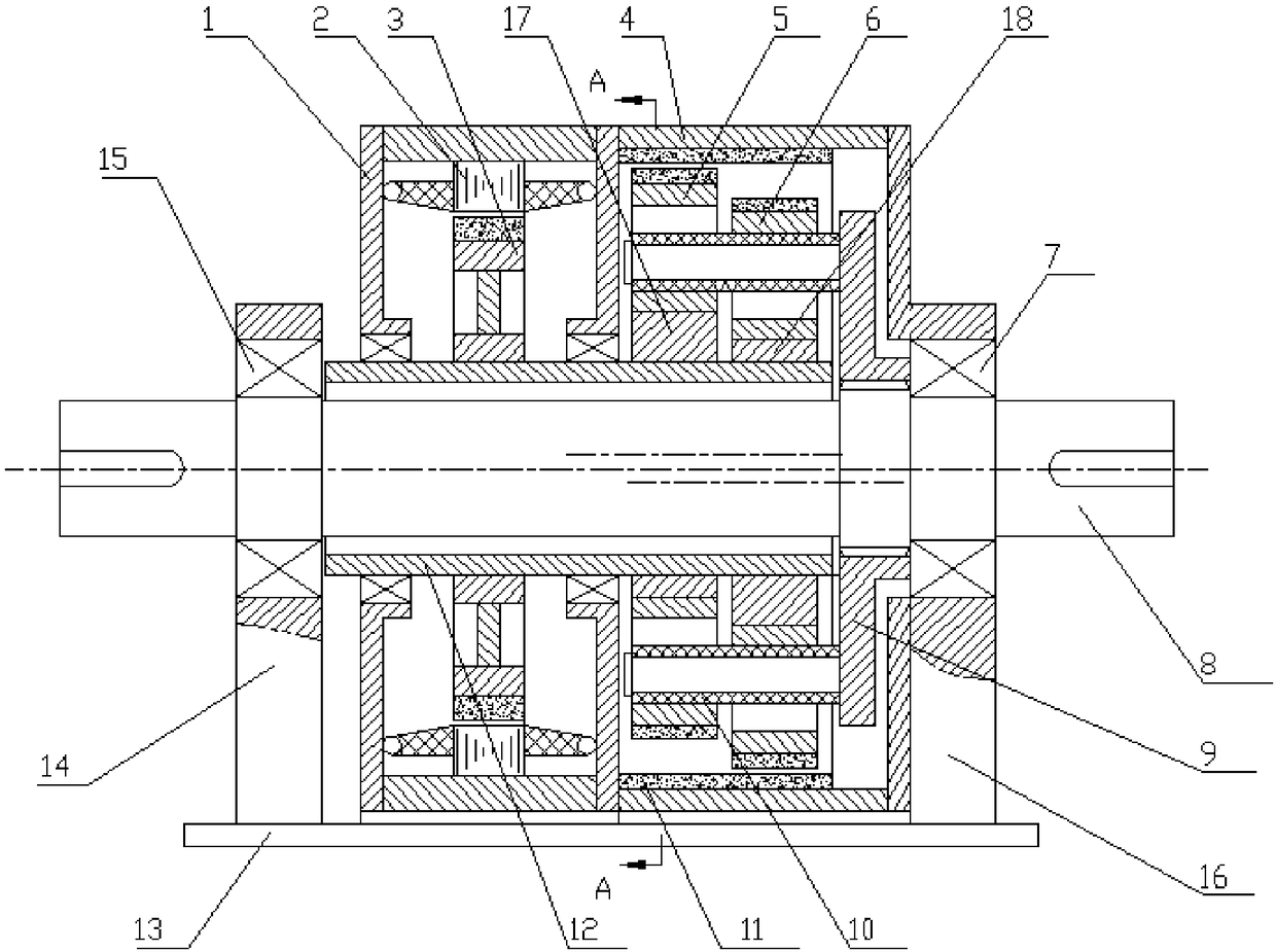
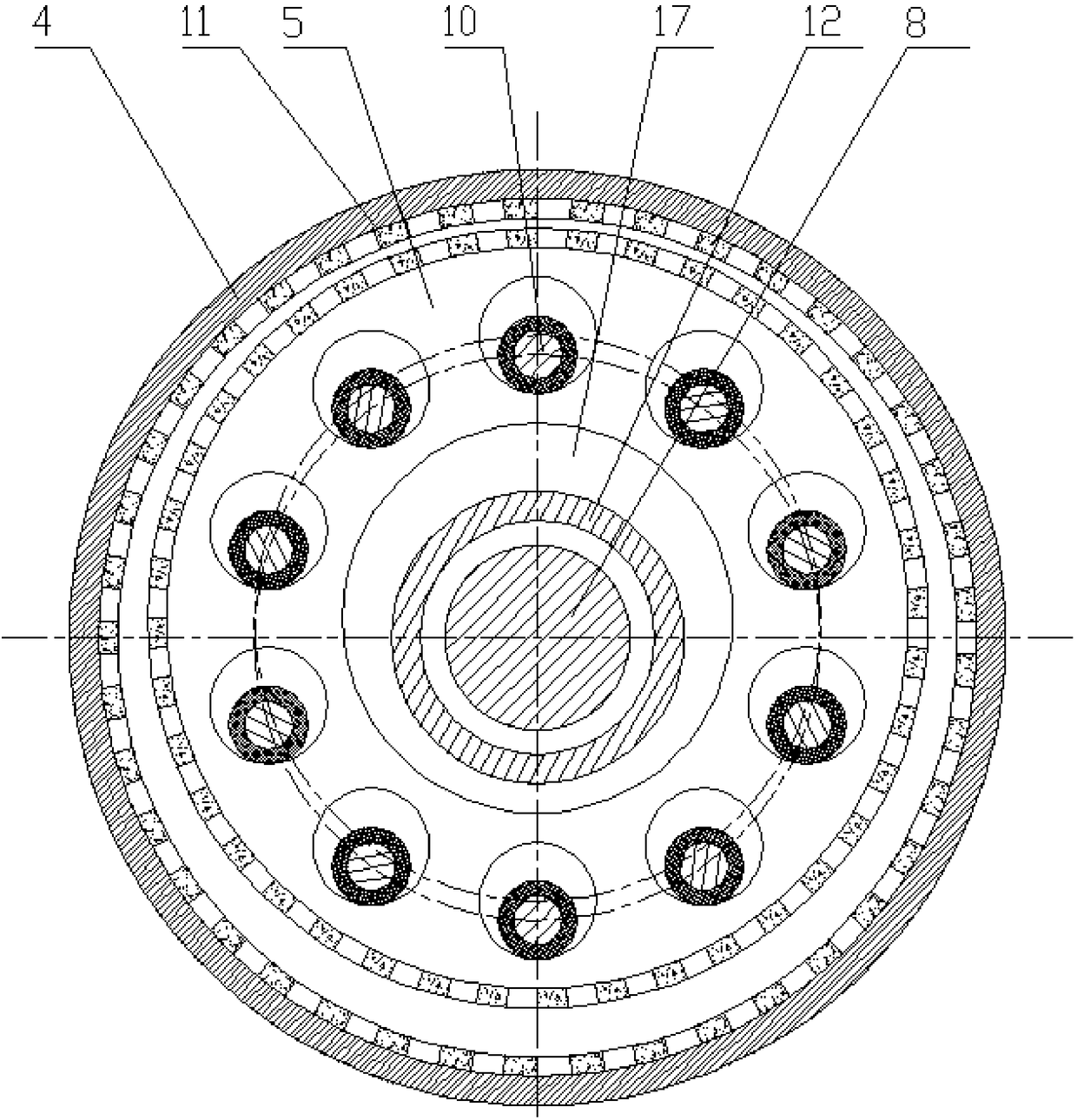
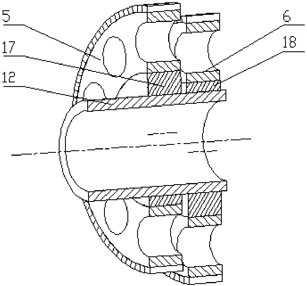
[0028] The present invention will be further described below in conjunction with the drawings. Such as Figure 1-3 As shown, an integrated permanent magnet transmission device with coaxial double-end output includes a permanent magnet motor assembly, a cycloid permanent magnet gear assembly and a power output assembly.

[0029] The permanent magnet motor assembly includes a housing I1, a stator 2 and a rotor 3; the stator 2 is pressed inside the housing, and the rotor 3 is pressed on the hollow shaft 12.

[0030] The cycloid permanent magnet gear assembly includes a housing II4, an outer permanent magnet ring 11, an inner permanent magnet ring I5, an inner permanent magnet ring II6, a power output disc 9, a pin shaft 10, an eccentric wheel I17 and an eccentric wheel II17 The outer permanent magnet ring 11 is pressed inside the housing II4; the inner permanent magnet ring I5 and the inner permanent magnet ring II6 respectively press the outer surfaces of the eccentric wheel I17 and...


PUM


Abstract

The invention discloses a coaxial two-terminal output integrated permanent magnet transmission device, which comprises a permanent magnet motor assembly, a cycloidal permanent magnet gear assembly anda power output assembly, wherein the permanent magnet motor assembly comprises a first shell, a stator and a rotor; and the cycloidal permanent magnet gear assembly comprises a second shell, an outerpermanent magnet coil, a first inner permanent magnet coil, a second inner permanent magnet coil, a power output disc, a pin shaft, a first eccentric wheel and a second eccentric wheel. A belt pulleyand a transmission node thereof are cancelled, thereby improving the transmission reliability and the transmission efficiency; the permanent magnet motor is adopted to replace an asynchronous motor,and as the work efficiency and the power factor of the permanent magnet motor are greatly higher than those of the asynchronous motor, the transmission efficiency of the system can be further improved; the cycloidal permanent magnet gear is adopted to replace a mechanical contact gear, and as the permanent magnet gear has the advantages of no friction, no wear, no noise and overload protection, the transmission reliability of the system can be further improved.

Description

Technical field [0001] The invention relates to a coaxial integrated permanent magnet transmission device, in particular to a coaxial double-end output transmission device integrating permanent magnet drive and permanent magnet speed change. Background technique [0002] In current industrial applications, a considerable part of the transmission system is composed of asynchronous motor + belt pulley + gear box, and most of the operating conditions are large inertia and variable load. In this type of transmission system, the asynchronous motor is the power source, and the pulley and gearbox are the deceleration devices. The requirements for the motor are large starting torque, high operating efficiency and a wide economic operating range. Therefore, such transmission systems generally use large-capacity asynchronous motors to meet the system’s large starting torque and high peak torque requirements, resulting in long-term operation of the motors in the system away from the rated p...

Claims


Application Information

Patent Timeline
Patent Type & Authority Applications(China)
IPC IPC(8): H02K49/10H02K7/10
CPCH02K7/10H02K49/102
Inventor 杨均悦葛研军
Owner DALIAN JIAOTONG UNIVERSITY
Learn More