Exhaust emission structure

A waste gas emission, square technology, applied in the direction of dispersed particle separation, chemical instruments and methods, dispersed particle filtration, etc., can solve the problems of affecting the effect of large flow of waste gas emission, affecting the effect of waste gas dust removal treatment, and the inability to switch gas efficiently, etc., to achieve Improved contact tightness, stable operation, and easy operation

Inactive Publication Date: 2018-06-26
CHONGQING YINSHENG MOLD
View PDF11 Cites 1 Cited by
  • Summary
  • Abstract
  • Description
  • Claims
  • Application Information

AI Technical Summary

Problems solved by technology

However, this kind of dust removal device cannot easily and efficiently switch the flow direction of the gas, which will not only affect the dust removal treatment effect on the exhaust gas, but also affect the emission effect on the large flow of exhaust gas
At the same time, it is also easy to cause blockage of the filter chamber, which poses a safety hazard

Method used


Image

  • Exhaust emission structure
  • Exhaust emission structure
  • Exhaust emission structure

Examples


Embodiment 1

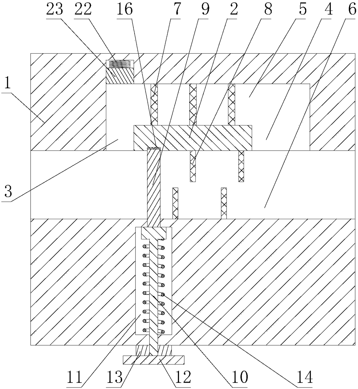
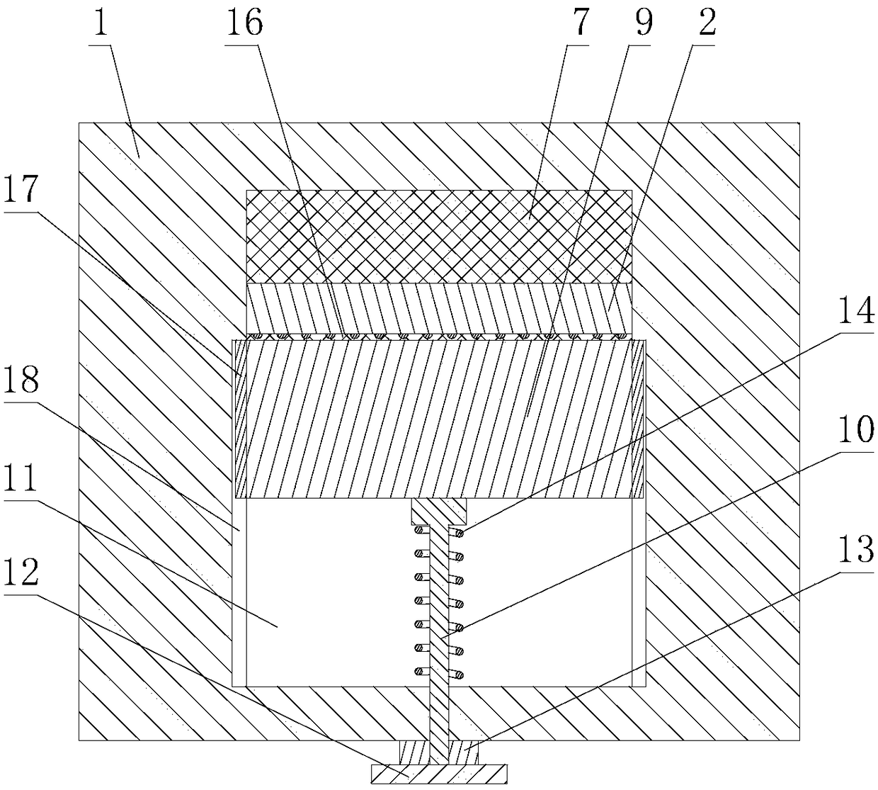
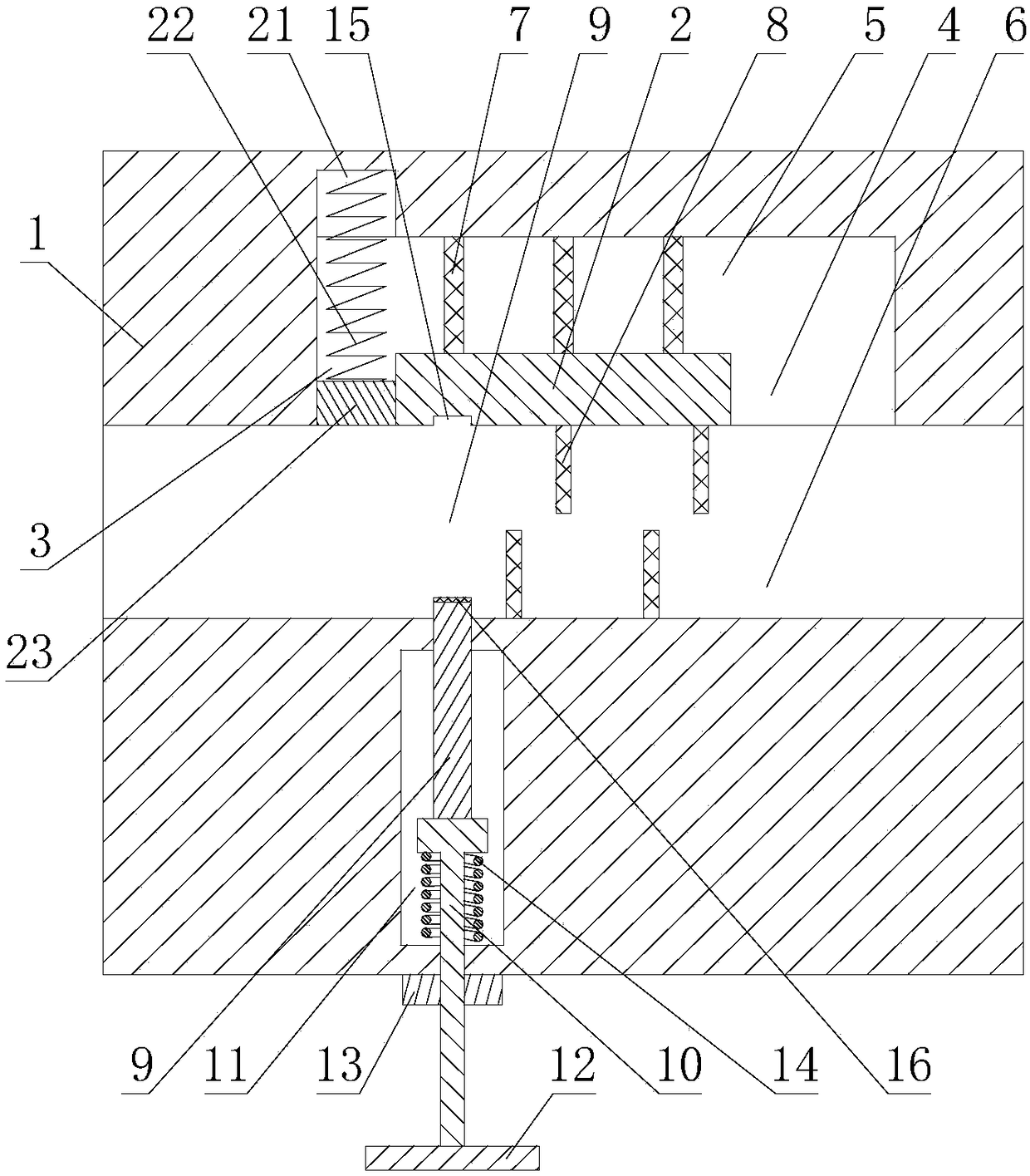
[0033] Such as Figure 1 to Figure 4 As shown, the exhaust gas discharge structure includes a square pipe 1 that is open at both ends of the left and right and is hollowly arranged. A partition 2 is arranged horizontally in the inner cavity of the square pipe 1. The left and right ends of the plate 2 are not connected to the inner wall of the square pipe 1, the left end of the partition 2 and the inner wall of the square pipe 1 jointly form a first port 3, and the right end of the partition 2 and the inner wall of the square pipe 1 jointly form a first opening 3. Two-way port 4;

[0034] The partition plate 2 divides the inner cavity of the square pipe 1 into a relatively independent filter cavity 5 and a discharge cavity 6 located below the filter cavity 5. The filter cavity 5 is provided with a plurality of front and rear direction setting and the area is equal to the first filter cavity 5 cross-sectional area. a filter screen 7;

[0035] The inner wall of the square pipe ...


PUM


Abstract

The invention discloses an exhaust emission structure, comprising a square pipeline, wherein a partition plate is transversely arranged in the inner cavity of the square pipeline; the partition platedivides the inner cavity of the square pipeline into a filter chamber and an emission chamber; the filter chamber is internally provided with a plurality of first filter screens; the inner wall of thesquare pipeline is provided with a mounting groove; and a first elastic member is arranged in the mounting groove and is connected with a plug. The exhaust emission structure further comprises a front square baffle and an adjusting rod. The pipe wall of the square pipeline is provided an accommodating chamber; the adjusting rod is sleeved by an adjusting ring; the square baffle is provided with apositioning strip; a positioning groove is arranged on the square pipeline; and a second elastic member is arranged in the accommodating chamber and acts on the adjusting rod so as to allow the upperend of the square baffle to be in close contact with the lower end of the partition plate. According to the invention, the square baffle can move up and down through cooperation between the second elastic member and the adjusting rod, so the effective switching of the flow direction of exhaust gas is realized; and the exhaust emission structure has the advantages of simple operation, stable running, safety and reliability.

Description

technical field [0001] The invention relates to an exhaust gas discharge structure. Background technique [0002] Industrial waste gas usually contains a lot of dust. For the sake of environmental protection, these industrial waste gases need to be dedusted before being discharged. The existing dust removal device is mainly a filter cavity arranged in the exhaust pipe, which absorbs the dust in the exhaust gas when the exhaust gas passes through the filter cavity. Exhaust gas encounters resistance as it passes through the filter cavity, resulting in reduced exhaust gas flow. [0003] At present, although there is a dust removal device that can adjust the exhaust gas flow through the air guide structure, it can meet the large flow exhaust demand when emergency exhaust is required. However, this kind of dust removal device cannot easily and efficiently switch the flow direction of the gas, which will not only affect the dust removal treatment effect on the exhaust gas, but a...

Claims


Application Information

Patent Timeline
Patent Type & Authority Applications(China)
IPC IPC(8): B01D46/00B01D46/12
CPCB01D46/0002B01D46/0047B01D46/12
Inventor 邱建华
Owner CHONGQING YINSHENG MOLD
Why Eureka
Try Eureka