Intelligent electric permanent magnetic chuck

An electric permanent magnet chuck, intelligent technology, applied in the direction of permanent magnets, circuits, magnets, etc., can solve the problem of not knowing whether there is a problem with the die hole, not being able to judge whether there is magnetism, and the size of the magnetic force cannot be judged, etc., to save mold replacement. And the effect of adjusting time, convenient operation and quick detection

Pending Publication Date: 2018-06-26
佛山市顺德区盛锵德磁科技有限公司
View PDF0 Cites 0 Cited by
  • Summary
  • Abstract
  • Description
  • Claims
  • Application Information

AI Technical Summary

Problems solved by technology

[0002] 1. The old electro-permanent magnetic sucker installs a large mold hole on the front or back of the mold, and several single magnetic groups are arranged in the mold hole, and then filled with resin, and then covered with a cover plate to waterproof , anti-deviation and other functions, the magnetic interference between the magnets of several single magnetic components placed in this large mold pit is too large, the suction force of the suction cup is weakened, and the forward transmission of the magnetic force is affected; 2. The old electropermanent magnetic chuck has no magnetic force detection coil. It is impossible to judge whether there is magnetism, the magnitude of the magnetic force cannot be judged, and it is impossible to know whether there is a problem with the die hole. It can only be judged by experience or tested one by one to detect faults; at the same time, it also increases the occurrence of safety accidents

Method used


Image

  • Intelligent electric permanent magnetic chuck
  • Intelligent electric permanent magnetic chuck
  • Intelligent electric permanent magnetic chuck

Examples


Embodiment Construction

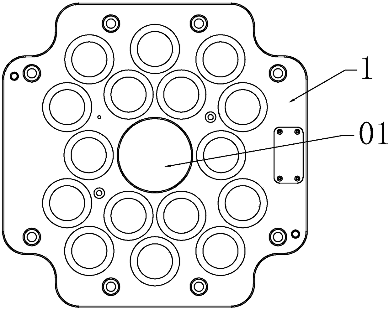
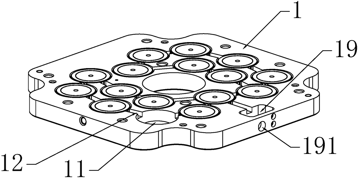
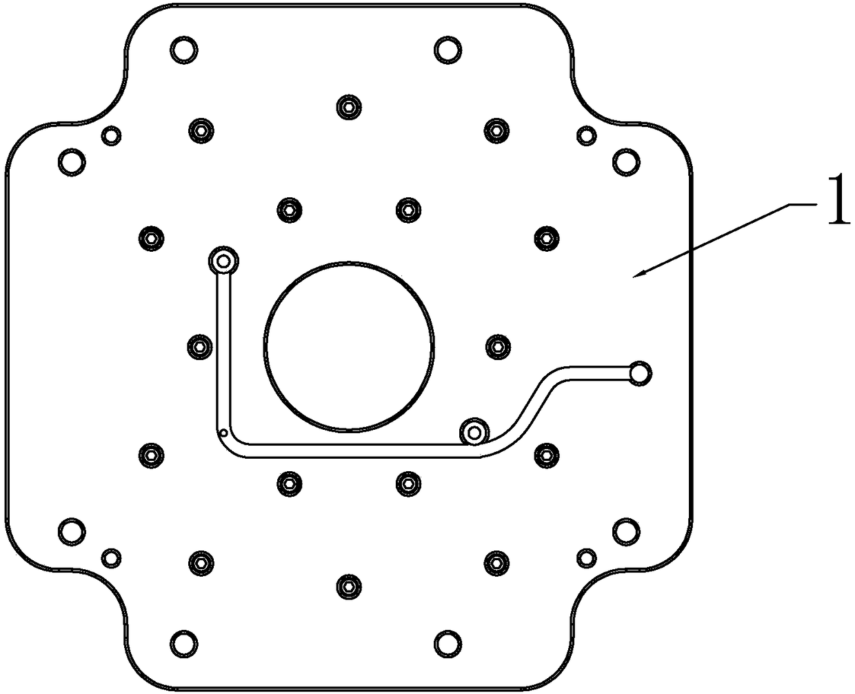
[0029]An intelligent electric permanent magnetic chuck, the electric permanent magnetic chuck device includes a template 1, the reverse side of the template 1 is provided with several blind die holes 11, the top between the blind die holes 11 is provided with a lead gap 12, each blind die hole 11 In the middle of the bottom, there is a cylinder 101 integrated with the template 1, and a surrounding groove 102 surrounding the cylinder 101 is formed between the cylinder 101 and the mold wall of the blind mold hole 11; the cylinder 101 is covered with a magnetic detection coil 103, the magnetic detection coil 103 is fixed on the groove bottom surrounding the groove 102; a NdFeB ring 104 is set on the cylinder 101, and a NdFeB ring 104, the magnetic detection coil 103 and the blind mold hole 11 mold wall are set with a Anti-magnetic interference snare 105, anti-magnetic interference snare 105 is to prevent the magnetic field lines (magnetic field) between the die holes from spreadin...


PUM


Abstract

The present invention discloses an intelligent electric permanent magnetic chuck. A plurality of blind die holes which are separated by die walls are arranged in a template, a lead gap is arranged onthe top of the die wall, a column which is arranged in the middle of the bottom of each blind die hole is connected with the template, a surrounding groove surrounding the column is arranged between the column and the die wall of the blind die hole, the structure of the blind die hole is simple, magnetic elements are arranged in the surrounding grooves in sequence, the surrounding grooves can rapidly check and align NdFeB rings which are formed by connecting a plurality of fan-shaped NdFeB elements. The outside of each NdFeB ring is an N pole, and the inside is an S pole. When the magnetic force is generated, reduced or increased, each NdFeB ring operates independently without mutually magnetic interference, the magnetic field grouping is not in mess, the magnetic field is released and recycled in a vertical circulation mode, the magnetic absorption ability is improved, the surrounding grooves can gather the magnetic force, one magnetic element is arranged in each blind die hole, so that the problem can be found easily, rapid detection and recovery can be realized, the die replacement time and adjustment time are shortened, the production efficiency is improved, and the productioncost is reduced.

Description

technical field [0001] The invention relates to the field of magnetic suction devices, in particular to an intelligent electric permanent magnetic chuck. Background technique [0002] 1. The old electro-permanent magnetic sucker installs a large mold hole on the front or back of the mold, and several single magnetic groups are arranged in the mold hole, and then filled with resin, and then covered with a cover plate to waterproof , anti-deviation and other functions, the magnetic interference between the magnets of several single magnetic components placed in this large mold pit is too large, the suction force of the suction cup is weakened, and the forward transmission of the magnetic force is affected; 2. The old electropermanent magnetic chuck has no magnetic force detection coil. It is impossible to judge whether there is magnetism, the magnitude of the magnetic force cannot be judged, and it is impossible to know whether there is a problem with the die hole. It can only...

Claims


Application Information

Patent Timeline
IPC IPC(8): H01F7/02
CPCH01F7/0257H01F7/0221
Inventor 李锵华方刘文
Owner 佛山市顺德区盛锵德磁科技有限公司
Why Eureka
Try Eureka