
Micro-macro two-stage driver and control method thereof

A driver and coil bobbin technology, applied in the field of macro-micro two-stage driver and its control, can solve the problems of small output force of piezoelectric ceramic driver, difficult to meet the needs of heavy loads, and connection error of macro-micro two-stage driver, and achieve output The effect of large force, simple structure and no connection error

Pending Publication Date: 2018-06-26
ANHUI UNIV OF SCI & TECH
View PDF0 Cites 5 Cited by
  • Summary
  • Abstract
  • Description
  • Claims
  • Application Information

AI Technical Summary

Problems solved by technology

[0003] At present, the macro-micro two-stage motion structure is usually arranged in series superposition, that is, the micro-motion mechanism is directly placed on the macro-motion mechanism, resulting in a complex overall structure of the workbench, and due to installation errors, the gap between the macro-micro two-stage drives There is a connection error
Piezoelectric ceramic actuators are the earliest and most mature driving devices. In the existing precision positioning workbench of macro-micro composite drive, piezoelectric ceramic actuators are mainly used as micro-displacement actuators. load requirements

Method used


Image

  • Micro-macro two-stage driver and control method thereof
  • Micro-macro two-stage driver and control method thereof
  • Micro-macro two-stage driver and control method thereof

Examples


Embodiment Construction

[0026] The following will clearly and completely describe the technical solutions in the embodiments of the present invention with reference to the accompanying drawings in the embodiments of the present invention. Obviously, the described embodiments are only some, not all, embodiments of the present invention. Based on the embodiments of the present invention, all other embodiments obtained by persons of ordinary skill in the art without making creative efforts belong to the protection scope of the present invention.

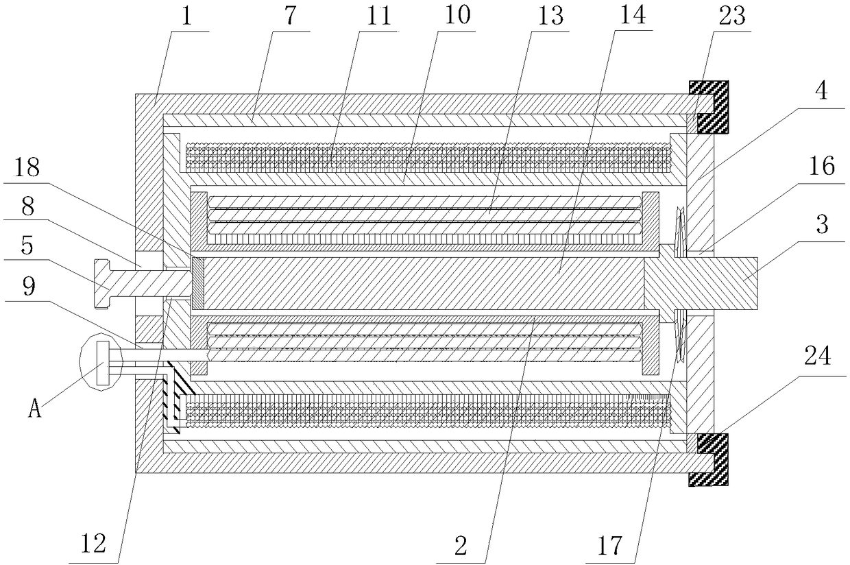
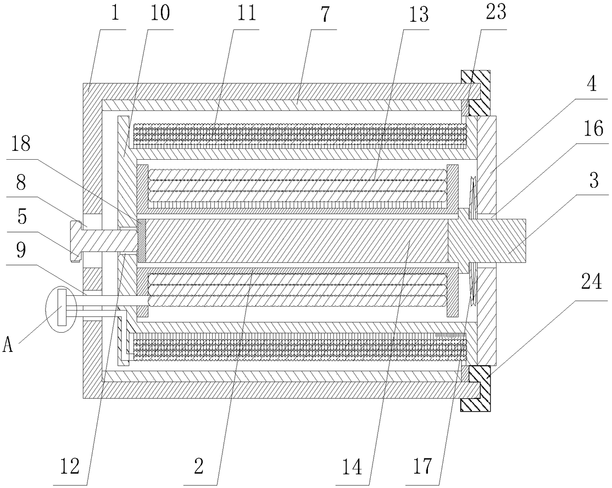
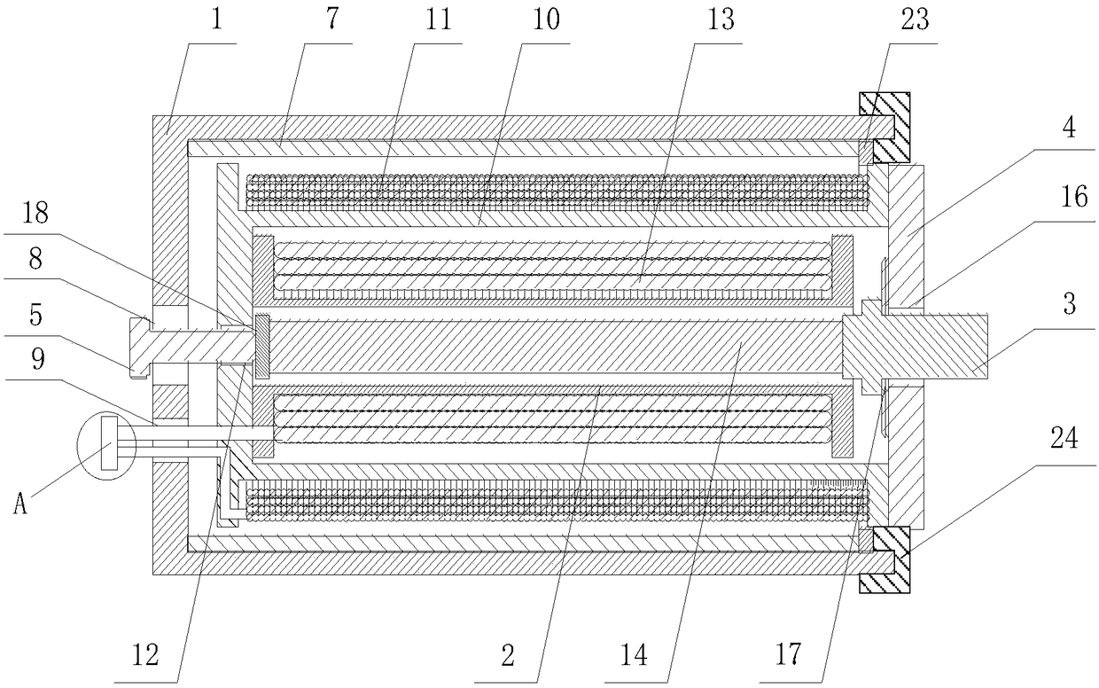
[0027] see Figure 1-6 , the present invention provides a technical solution: a macro and micro two-stage driver, including a housing 1, a second bobbin 2, an output rod 3, an end cover 4, a pre-tightening screw 5 and a terminal 6, and the housing 1 is internally installed There is a permanent magnet cylinder 7, and a circular hole 8 is opened in the center of one side of the shell 1, and a power transmission hole 9 is opened on one side of the circular hole 8...


PUM


Abstract

The invention discloses a micro-macro two-stage driver and a control method thereof, and belongs to the technical field of precision positioning. The micro-macro two-stage driver comprises an outer casing, a second coil skeleton, an output rod, an end cover, a pre-tightening screw and a wiring terminal, wherein a permanent magnet cylinder is arranged in the outer casing to provide a radial magnetic field; a first coil skeleton is arranged in the permanent magnet cylinder, and is used for winding a first coil; a second coil skeleton is arranged in the first coil skeleton, and is used for winding a second coil; a giant magnetostictive telescopic rod is arranged in the second coil skeleton; the end cover is fixedly connected with the first coil skeleton through a bolt; an output hole is formed in the center of the end cover; the output rod penetrates through the output hole; the pre-tightening screw penetrates through the circular hole and is connected with a threaded hole by threads; both ends of the first coil are respectively connected with a first conducting wire and a second conducting wire. The micro-macro two-stage driver has the advantages that by adjusting the size of currentwhich is led into the first coil to control the macro-moving of the driver, and adjusting the size of current which is led into the second coil to control the micro-moving of the driver, the large-travel and high-accuracy drive effect can be realized.

Description

technical field [0001] The invention belongs to the technical field of precise positioning, and in particular relates to a macro-micro two-stage driver and a control method thereof. Background technique [0002] With the vigorous development of the high-end equipment manufacturing industry, there is an increasing demand for precision positioning worktables with large stroke, high precision, heavy load, and fast response. Due to the contradiction between macro and micro drivers, more and more drivers are used in engineering applications. [0003] At present, the macro-micro two-stage motion structure is usually arranged in series superposition, that is, the micro-motion mechanism is directly placed on the macro-motion mechanism, resulting in a complex overall structure of the workbench, and due to installation errors, the gap between the macro-micro two-stage drives There is a connection error. Piezoelectric ceramic actuators are the earliest and most mature driving devices...

Claims


Application Information

Patent Timeline
IPC IPC(8): H02K41/03H02N2/02H02P7/02H02N2/06
CPCH02K41/031H02N2/02H02N2/06H02P7/02H02P2207/05
Inventor 喻曹丰姜志王传礼陈清华解甜杨林建徐彬
Owner ANHUI UNIV OF SCI & TECH
Learn More