Mobile pneumatic type grain pile accumulated heat discharge mechanism

A pneumatic, heat-dissipating mechanism technology, used in climate change adaptation, agricultural machinery and implements, fruit suspension devices, etc., can solve problems such as grain damage, reduce workload, strengthen distribution, and ensure the quality of grain storage.

Inactive Publication Date: 2018-06-29
郑州龙威电气安装有限公司
View PDF0 Cites 4 Cited by
  • Summary
  • Abstract
  • Description
  • Claims
  • Application Information

AI Technical Summary

Problems solved by technology

[0004] The purpose of the present invention is: in order to solve the problem that most of the existing agitating grain heat dissipation devices use stirring blades, which easily cause grain damage during the heat dissipation process, the present invention provides a mobile pneumatic grain pile heat removal mechanism

Method used


Image

  • Mobile pneumatic type grain pile accumulated heat discharge mechanism
  • Mobile pneumatic type grain pile accumulated heat discharge mechanism
  • Mobile pneumatic type grain pile accumulated heat discharge mechanism

Examples


Embodiment 1

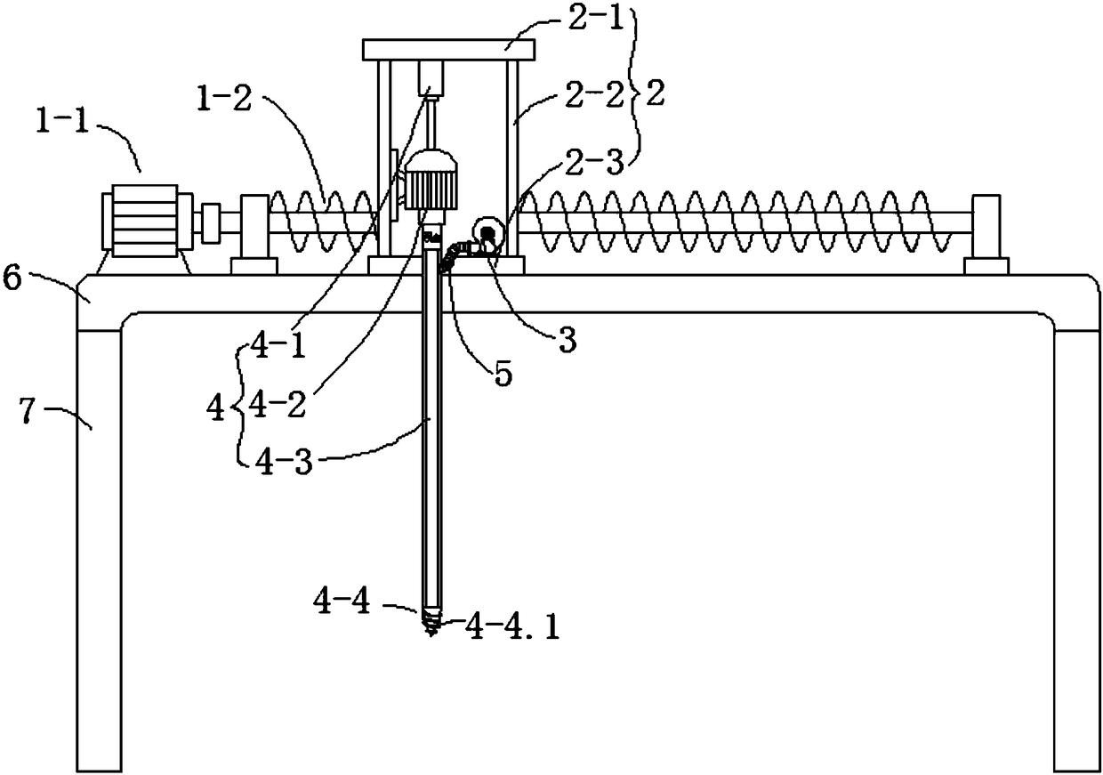
[0020] Such as Figure 1 to Figure 3 As shown, this embodiment provides a mobile pneumatic grain pile heat removal mechanism, including two symmetrically arranged support plates 7 and a mounting plate 6 horizontally erected on the top of the two support plates 7, and the mounting plate 6 is provided with a horizontal movement mechanism 1. The horizontal moving mechanism 1 is connected with a moving seat 2, and the moving seat 2 is provided with a lifting and cooling mechanism 4 and a blower 3 connected with the lifting and cooling mechanism 4. The lifting and cooling mechanism 4 includes a forward and reverse motor 4-2, which drives the The lifting cylinder 4-1 that the motor 4-2 moves up and down and the ventilation rod 4-3 connected to the output shaft of the forward and reverse motor 4-2, the mounting plate 6 is dug with a through groove 6 for the horizontal movement of the ventilation rod 4-3 -1, the interior of the ventilation rod 4-3 is vertically provided with a ventila...

Embodiment 2

[0023] This embodiment is further optimized on the basis of Embodiment 1, specifically:

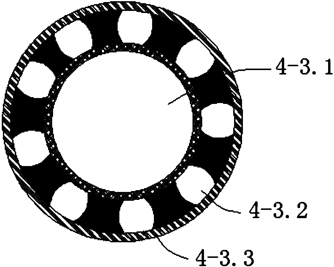
[0024] The outer wall of the ventilation rod 4-3 is provided with a breathable film layer 4-3.3 for preventing grain from entering the ventilation rod 4-3 from the ventilation hole 4-3.2, so as to prevent the grain from entering the ventilation rod 4-3 and affecting the normal operation of the equipment , to ensure the efficiency of the cooling work.

Embodiment 3

[0026] This embodiment is further optimized on the basis of Embodiment 2, specifically:

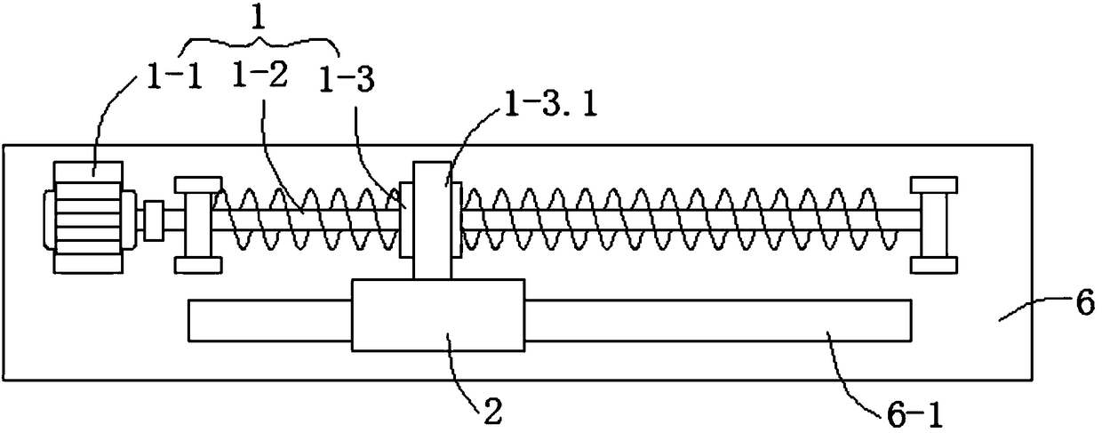
[0027] The horizontal movement mechanism 1 includes a drive motor 1-1, a ball screw 1-2 fixedly connected to the output shaft of the drive motor 1-1, and a ball set on the ball screw 1-2 to match the ball screw 1-2. The nut 1-3 and the ball nut 1-3 are provided with a connecting block 1-3.1 fixedly connected with the moving seat 2.

[0028] The moving seat 2 includes a moving bottom plate 2-3 slidingly fitted with the mounting plate 6, two vertical plates 2-2 symmetrically arranged on the moving bottom plate 2-3, and a horizontal plate 2-2 erected on the top of the two vertical plates 2-2. 1. The forward and reverse motor 4-2 is vertically installed on one of the vertical plates 2-2, the lifting cylinder 4-1 is placed upside down on the horizontal plate 2-1, and the piston rod of the lifting cylinder 4-1 is connected with the positive and negative motor 4 -2 is fixedly connected, and a t...


PUM


Abstract

The invention discloses a mobile pneumatic type grain pile accumulated heat discharge mechanism and relates to the technical field of grain storage equipment. The mechanism disclosed by the inventioncomprises two support plates which are symmetrically arranged and a mounting plate erected on the two support plates, wherein a horizontal moving mechanism is arranged on the mounting plate and is connected with a moving seat, a lifting heat dissipation mechanism and an air blower are arranged on the moving seat; the lifting heat dissipation mechanism comprises a positive and negative rotation motor, a lifting cylinder driving the positive and negative rotation motor to move up and down and a vent rod connected with the positive and negative rotation motor; a through slot for the vent rod to horizontally move is dug in the mounting plate, a vent chamber is vertically arranged in the vent rod, a plurality of vent holes communicated with the vent chamber are formed in the side wall of the vent rod, and the output end of the air blower is communicated with the vent chamber by a flexible hose. According to the invention, air is blown into the vent chamber by the air blower, then the air isejected from the vent rod via the vent holes, so that under the condition of ensuring that grains are not damaged, heat accumulated in the grain pile can be dissipated, and therefore, grain storage quality is ensured.

Description

technical field [0001] The invention relates to the technical field of grain storage equipment, and more specifically relates to a mobile pneumatic grain pile heat removal mechanism. Background technique [0002] Grain storage is related to military supplies, people's livelihood and social stability. More than one-third of my country's grain is stored in the hands of farmers. It is of great significance to optimize farmers' grain storage devices. With the improvement of the storage level of farmers, the original method of grain storage is gradually replaced by the simple color steel granary from the accumulation of woven bags. However, the disadvantage of the current simple color steel granary is that there is no reasonable ventilation and heat dissipation device. In summer, solar radiation and grain respiration heat make the warehouse temperature significantly higher than the outside temperature. The increase in warehouse temperature accelerates the deterioration of grain q...

Claims


Application Information

Patent Timeline
Patent Type & Authority Applications(China)
IPC IPC(8): A01F25/16A01F25/22
CPCA01F25/16A01F25/22Y02A40/51
Inventor 王波
Owner 郑州龙威电气安装有限公司
Why Eureka
Try Eureka