
Modular combined type medical semi-automatic drainage metering device

A metering device and a combined technology, applied in the direction of suction containers, suction devices, and other medical devices, can solve the problems of polluting the fingers of the discharger, increasing medical expenses, and scrapping the device, and achieve the effect of avoiding pollution

Inactive Publication Date: 2018-06-29
CONOD MEDICAL
View PDF20 Cites 4 Cited by
  • Summary
  • Abstract
  • Description
  • Claims
  • Application Information

AI Technical Summary

Problems solved by technology

[0006] The above-mentioned CN1282451C, CN200994924Y and CN202207340U, as well as CN2778276Y (a urine storage and metering device) not mentioned above, all have the following deficiencies: First, because the only hard box is used, the urine storage capacity is limited, However, if the volume of the box is increased, it is easy to cause an increase in manufacturing and use costs, and the cost of raw materials is large, which will eventually lead to an increase in medical expenses borne by the patient; The precision measurement effect is compatible with the result. Third, due to the unreasonable structure of the liquid discharge valve of the box body, it is easy to be damaged during the packaging, transportation and storage of the finished product, and once the liquid discharge valve is damaged, the entire device will be scrapped; Fourth, because it does not have the function of random sampling of drainage fluid, it causes confusion for medical staff when sampling
[0007] The deficiencies in the above four aspects are eliminated by the "Mother-in-Child Medical Semi-automatic Drainage Metering Device" announced by the invention patent authorization announcement number CN103203044B, and this CN103203044B objectively fulfills the technical effects of the five aspects recorded in the technical effect column of its manual , but there are still the following shortcomings: one, because the box body drain valve for discharging the liquid in the box body cavity of the box body such as urine is composed of a valve seat, a valve sleeve, a spiral sleeve and a valve core, the valve seat passes through the The hot-melt welding method is fixed to the bottom wall of the box body, the valve sleeve is inserted into the valve seat cavity of the valve seat and communicates with the box body cavity of the box body, and the lower end of the valve sleeve extends out of the valve seat cavity of the valve seat, and the spiral sleeve Cooperate with the thread on the outer wall of the lower end of the valve sleeve, the valve core forms an integrated structure with the spiral sleeve cavity through the valve core seat, when discharging liquid, pinch and rotate the spiral sleeve with your fingers to make the valve core leave the right valve The plugging of the sleeve pipe is the same as vice versa, so no matter whether it is draining or stopping the draining, the operation of the helical sleeve is very laborious (for details, refer to paragraphs 0030 to 0031 of the specification of this patent); The position of the liquid discharge valve of the body is located at the bottom of the box body, and because the finger is required to rotate the screw sleeve when discharging the liquid, and because the volume of the liquid discharge valve of the whole box body is small, a little carelessness will pollute the liquid when discharging the liquid. The finger of the person who discharges the liquid, especially when the thread fit between the inner wall of the spiral sleeve and the outer tube of the valve sleeve is not good, the liquid will leak from the gap between the two during the discharge process, and it will become dirty and discharge The operator (usually the accompanying person of the patient); third, since the spiral sleeve needs to be returned to the fully tightened state with the valve sleeve after the liquid is discharged, so that the valve core can fully block the liquid outlet of the valve sleeve , so the tightening degree of the spiral sleeve and the valve casing is determined by the hand feel, and the perception and judgment of the aforementioned tightening degree are often different for the escorts of different physical abilities, different age groups and even different genders, so in clinical use During the process, it is difficult to avoid the abnormal dripping of the liquid in the box body cavity from the box body liquid discharge valve; fourth, because the pair of hooks and the hook plate of the structural system of the bag hanging device form an integrated structure, and the hook plate passes through its lower part The connecting strip formed by the extension is implanted in the hanging bag cavity of the liquid storage bag, and because the structural system of the bag hanging device also has a hanging rope, it is convenient to choose between a pair of hooks and a hanging rope according to the actual situation in actual use. (For details, refer to paragraphs 0039 to 0040 of the specification of this patent). Therefore, when hanging with a lanyard, a pair of hooks not only becomes a redundant burden, but also interferes with the vicinity of the hanging. When hitting the hook, it will cause the liquid storage bag and the box body to sway, which will affect the precision measurement effect of the precision metering chamber, because during the aforementioned swaying process, the liquid in the precision metering chamber will flow abnormally from the overflow port of the partition plate In the large-capacity metering chamber of the box body; fifthly, because it is only hung by the aforementioned bag hanging device connected to the upper part of the liquid storage bag in the use state, the balance of the liquid storage bag and the box body is relatively lacking, and the degree of balance The pros and cons will also affect the measurement effect

Method used


Image

  • Modular combined type medical semi-automatic drainage metering device
  • Modular combined type medical semi-automatic drainage metering device
  • Modular combined type medical semi-automatic drainage metering device

Examples


Embodiment Construction

[0031] In order to understand the technical essence and beneficial effects of the present invention more clearly, the applicant will describe in detail the following examples, but the descriptions of the examples are not intended to limit the solutions of the present invention. Equivalent transformations that are only formal but not substantive should be regarded as the scope of the technical solution of the present invention.

[0032] In the following descriptions, all directional or azimuth concepts such as up, down, left, right, front, back, vertical, horizontal, clockwise, and counterclockwise are aimed at figure 1 As far as the position and state of the present invention are concerned, it cannot be understood as a special limitation on the technical solution provided by the present invention.

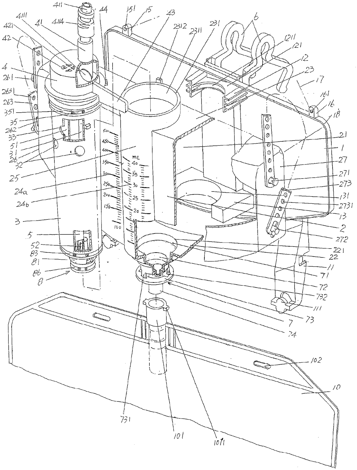
[0033] See figure 1 , shows a box seat 1 and a box body 2 molded by medical non-toxic grade plastics such as medical PVC, a pair of liquid collection bag hanging legs 11 are exten...


PUM


Abstract

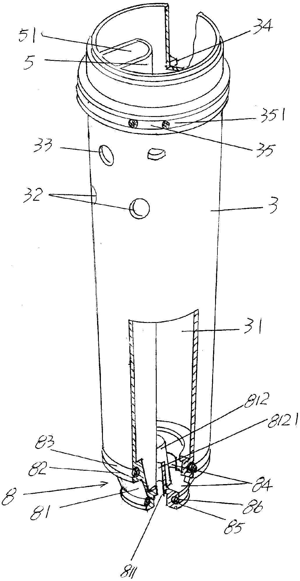
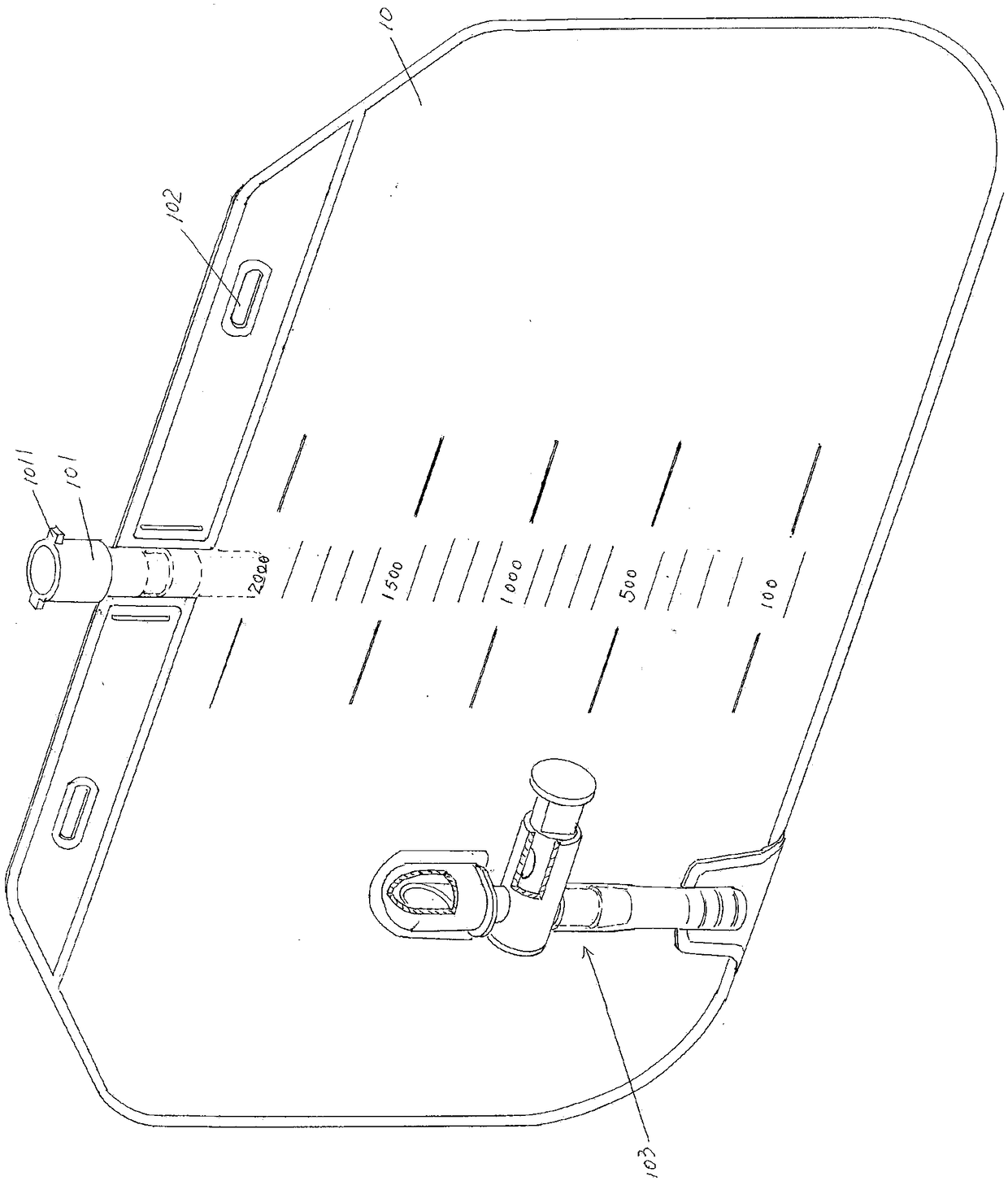
Disclosed is a modular combined type medical semi-automatic drainage metering device. The device comprises a box base, a box body, a precision metering cylinder, a drainage pipe matched connection base, a vent pipe and a pair of hooks. A pair of liquid collecting bag hanging feet are arranged at the lower portion of the box base, and a box cavity bottom drainage outlet is formed in the bottom wallof the box body; the precision metering cylinder is arranged inside a box cavity; the drainage pipe matched connection base is fixedly connected with the top of the precision metering cylinder; the vent pipe is longitudinally fixed to the interior of the cylinder cavity, and the hooks are arranged on the side back onto the box body. The device is characterized in that a precision metering cylinder matched base is arranged at the upper portion of the side, facing the box body, of the box base, a precision metering cylinder limiting base is arranged on the side, facing the box body, of the boxbase, a precision metering cylinder sealing holder ring is arranged on the top wall of the box body, a drainage mechanism is arranged on the bottom wall of the box body, a piston type sealing mechanism is arranged at the lower portion of the precision metering cylinder and matched with the drainage mechanism, and a spanner extends on the side wall of the drainage pipe matched connection base. Thedevice is simple in structure, capable of avoiding contaminations generated on fingers of an operator during the liquid draining operation, good in modularized effect, capable of avoiding seepage dripping under the non-liquid-draining state, capable of ensuring he metering accuracy and good in box body balance effect.

Description

technical field [0001] The invention belongs to the technical field of medical equipment, and in particular relates to a modular combined semi-automatic medical drainage metering device. Background technique [0002] The aforementioned medical semi-automatic drainage metering device is used in medical clinics to measure the urine of catheterized patients and also to measure the drainage fluid of patients after thoracoabdominal surgery, so that medical staff can understand the pathological conditions of patients and rationally adjust medication and medication according to the pathological conditions. treatment solutions. [0003] Earlier, medical clinical drainage generally used drainage bags, which consisted of plastic tubes (also known as drainage tubes) and plastic liquid storage bags with large-capacity measurement marks. This type of drainage bag can only roughly estimate the patient's volume because it cannot be measured correctly. The amount of urine or drainage fluid...

Claims


Application Information

Patent Timeline
IPC IPC(8): A61M1/00
CPCA61M2202/0496A61M2205/3334A61M1/67A61M1/734A61M1/84A61M2202/0014
Inventor 沈建东
Owner CONOD MEDICAL
Learn More