Metallurgical nozzle for protection pouring and method for protection pouring

A technology for protecting pouring and nozzles, applied in metal processing equipment, manufacturing tools, casting melt containers, etc. The effect of cloth science, shock reduction and liquid level calming

Active Publication Date: 2020-01-31
秦皇岛宏兴钢铁有限公司
View PDF1 Cites 0 Cited by
  • Summary
  • Abstract
  • Description
  • Claims
  • Application Information

AI Technical Summary

Problems solved by technology

At present, under the long nozzle diversion mode, the metallurgical process of the tundish is relatively long, and the effect of removing inclusions in depth is not obvious
[0004] Chinese patent CN2853235Y discloses a "bell-jar-type shroud for continuous casting", and proposes a bell-jar-type shroud in which the diameter of the continuous casting nozzle gradually increases in the direction of steel flow. The composition includes a long nozzle made of refractory materials. The nozzle body has a sealing ring made of refractory fiber on the inner side of the upper end, and the outer part of the upper end is wrapped by a steel shell. The nozzle body and the lower end of the steel shell are filled and sealed with refractory mud. There is a blowing pipe on the steel shell, which is under the neck of the body. After the diameter gradually increases, the bell jar shape is formed stably. This kind of nozzle is conducive to the complete dispersion of the drainage sand, and can effectively reduce the speed of the steel flow rushing into the tundish. However, the molten steel described in the disclosed patent documents is still a beam. The flow of molten steel still has a large erosion of refractory materials, and the agitation of the molten steel in the tundish by the pouring flow is still severe, and it has no effect on the removal of molten steel inclusions
[0005] It can be seen from the analysis that the current tundish metallurgy is based on the smelting under the action of high-speed steel flow at the long nozzle, and there are some problems caused by molten steel flow. Therefore, this application proposes a new protective pouring special metallurgical nozzle and its method

Method used


Image

  • Metallurgical nozzle for protection pouring and method for protection pouring

Examples


Embodiment 1

[0025] Embodiment 1 protects the metallurgical nozzle for pouring

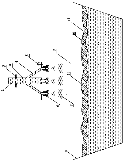
[0026] see figure 1 , the metallurgical nozzle is composed of a rainwater nozzle and a rainification chamber. The rainwater nozzle is composed of a sliding nozzle 2, a main nozzle 3, a branch nozzle 4, and an air nozzle 6. A sliding nozzle 2 is arranged above the main nozzle 3. The sliding nozzle 2 can be Slide up and down on the main nozzle 3 to control the flow of molten steel. 4 or 9 branch nozzles 4 are arranged below the main nozzle 3, a plurality of branch nozzles 4 are integrated with the main nozzle 3, and the lower ends of the main nozzle 3 and the branch nozzles 4 are respectively connected to the air nozzles 6. The rainwater outlet is located above the rainification chamber 8, and the air nozzle 6 is located above the rainification chamber 8. The rainification chamber 8 is a sealed refractory container filled with high-temperature argon gas and equipped with a pressure regulating valve. The lower ...

Embodiment 2

[0028] Embodiment 2 The method of using the above-mentioned metallurgical nozzle protection pouring

[0029] The molten steel 1 in the ladle passes through the main nozzle 3 and flows into each branch nozzle 4. In the rain chamber 8 with the function of protecting pouring, the gas nozzle 6 sprays high-temperature argon gas to rain the steel flow out of each branch nozzle 4 into droplets. , the steel droplets fall and pass through the 12 layers of refining slag in the lower part of the rain chamber 8, the inclusions and gases in the droplets are removed, and the clean steel droplets enter the static flow tundish 9.

Embodiment 3

[0030] Example 3 field application experiment

[0031] 1. In a billet continuous casting pouring example in a certain iron and steel plant, the rainification nozzle and the rainification chamber of the present invention used, the inner diameter of the main nozzle of the rainification nozzle is 80mm, the inner diameter of the branch nozzle is 40mm, and the number of branch nozzles is 4 , the arrangement of branch nozzles is uniform scattering in the center; the rain chamber is a sealed refractory container filled with high-temperature argon gas and equipped with a pressure regulating valve.

[0032] The method of protective pouring of molten steel is that the molten steel in the ladle passes through the main nozzle and flows into four branch nozzles. In the rain chamber with the function of protective pouring, the air nozzle sprays high-temperature argon gas to rain the steel flow out of the branch nozzles into droplets. , the average diameter of the droplet is 8mm, the steel d...


PUM


Abstract

Disclosed are a metallurgy nozzle for protective casting and a method for protective casting. The metallurgy nozzle comprises a raining nozzle and a raining chamber. A sliding nozzle is arranged abovea main nozzle of the raining nozzle, a plurality of branch nozzles are arranged below the main nozzle, the multiple branch nozzles and the main nozzle are integrated, the lower ends of the main nozzle and the branch nozzles are connected with blast nozzles separately, the raining nozzle is located above the raining chamber, and the lower end of the raining chamber is located in a tundish containing molten steel. The molten steel passes through the main nozzle and flows into the branch nozzles in a shunting mode; in the raining chamber, high-temperature argon ejected by the blast nozzles turnssteel streams flowing out of the branch nozzles into droplets in a raining mode, the steel droplets penetrate through a refining slag layer on the lower portion of the raining chamber, impurities andgas in the droplets are removed, and the clean steel droplets enter into the tundish. The structural arrangement of the raining nozzle is scientific, and after the steel streams are turned into the droplets, impact to a lining of the tundish is reduced; and since conventional devices such as a retaining wall and a retaining dam are omitted in the tundish, the defects in the prior art are overcome, the flow path of the steel streams is shortened, and flowing is peaceful.

Description

technical field [0001] The invention relates to a metallurgical nozzle for steelmaking and continuous casting, in particular to a metallurgical nozzle for protecting pouring and a method for protecting pouring, and provides a simple and efficient new metallurgical method for molten steel tundish. Background technique [0002] During the continuous casting process, the molten steel in the ladle is generally poured into the tundish through the long nozzle. [0003] Conventional shrouds are generally straight cylinders, made of fused quartz and aluminum carbon. The shroud’s function is to prevent secondary oxidation, restrain steel flow and heat insulation during molten steel pouring. Because the steel flow at the outlet of the shroud is The flow velocity is high and the kinetic energy is large. Generally, a turbulence suppressor needs to be installed at the bottom of the tundish to slow down the impact of molten steel. At the same time, under the constraints of retaining walls...

Claims


Application Information

Patent Timeline
Patent Type & Authority Patents(China)
IPC IPC(8): B22D41/22B22D41/58
CPCB22D41/22B22D41/58
Inventor 赵定国艾立群王书桓崔小杰张福君
Owner 秦皇岛宏兴钢铁有限公司
Why Eureka
Try Eureka