
Processing device and processing method of simulated groove in inner wall of conical water inlet pipe of water pump

A processing device and water inlet pipe technology, which is applied to metal processing equipment, manufacturing tools, milling machine equipment details, etc., can solve problems such as pipes that are not suitable for taper-shaped water pump inlet pipes, and achieve operation quality assurance, high precision, and scope of application wide effect

Pending Publication Date: 2018-06-29
ZHEJIANG UNIV OF TECH
View PDF5 Cites 14 Cited by
  • Summary
  • Abstract
  • Description
  • Claims
  • Application Information

AI Technical Summary

Problems solved by technology

However, the existing groove processing device can only process straight pipes with the same inner diameter, and is not suitable for tapered pipes such as water pump inlet pipes.

Method used


Image

  • Processing device and processing method of simulated groove in inner wall of conical water inlet pipe of water pump
  • Processing device and processing method of simulated groove in inner wall of conical water inlet pipe of water pump
  • Processing device and processing method of simulated groove in inner wall of conical water inlet pipe of water pump

Examples


Embodiment 1

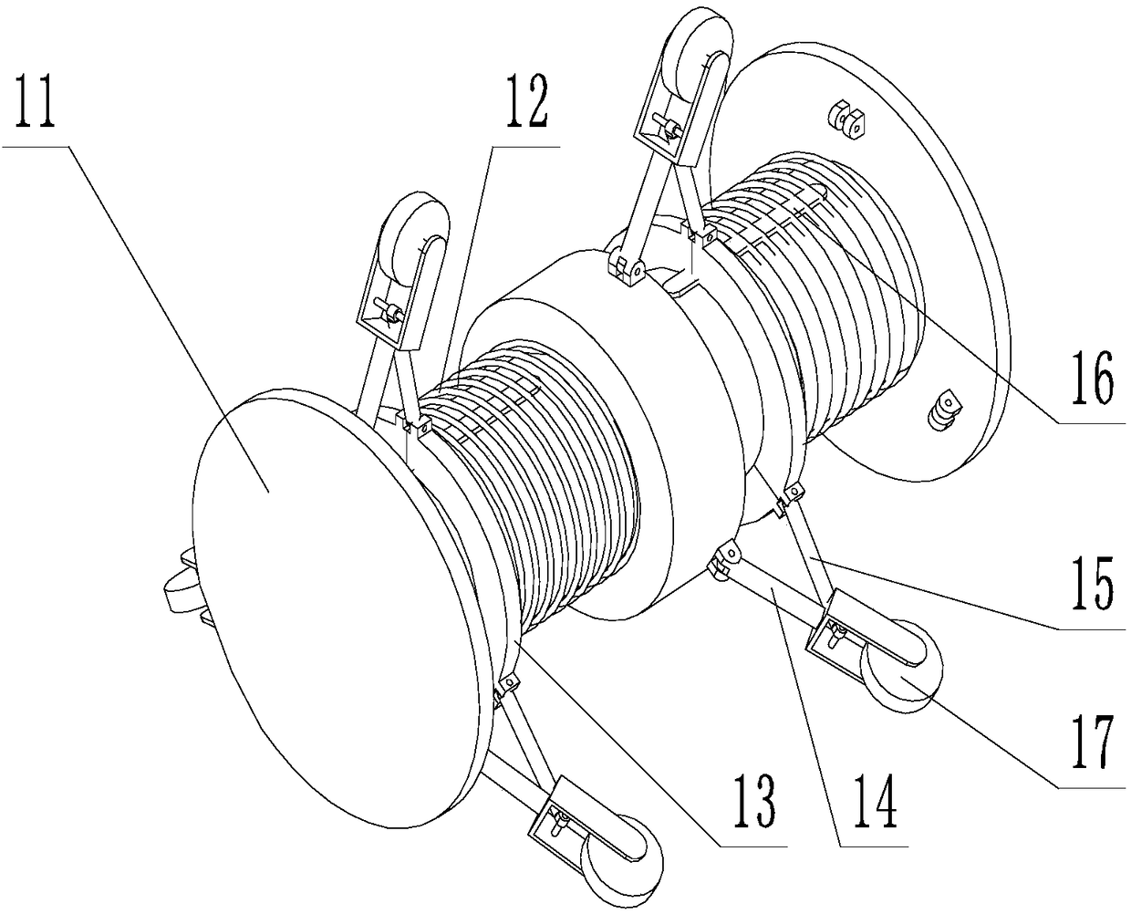
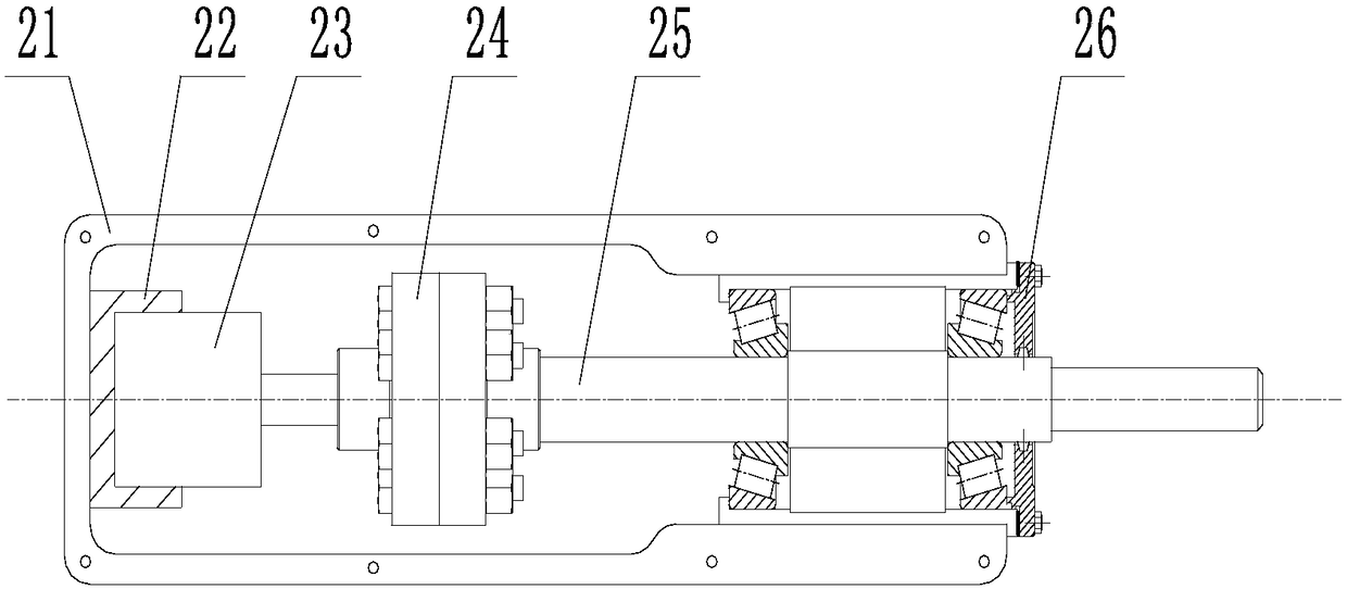
[0040] Embodiment 1 A processing device for bionic grooves on the inner wall of a conical water inlet pipe of a water pump according to the present invention includes an auxiliary support mechanism 1 for supporting the whole processing device to snap into the conical water inlet pipe of the water pump, and an auxiliary support mechanism 1 for driving the processing mechanism around Rotating rotary mechanism 2, a processing mechanism 3 for processing bionic grooves on the inner wall of the conical water inlet pipe of the water pump, and a feeding mechanism 4 for driving the entire processing device to advance axially along the inner wall of the pipe, the auxiliary support mechanism 1 and The rotating mechanism 2 is fixedly connected by bolts; the output end of the rotating mechanism 2 is connected to one of the shaft ends of the processing mechanism 3; the other shaft end of the processing mechanism 3 is connected to the action end of the feeding mechanism 4 , to realize the adv...

Embodiment 2

[0053] Embodiment 2 The processing method of using the processing device for the bionic groove on the inner wall of the conical water inlet pipe of a water pump described in Embodiment 1 includes the following steps:

[0054] (1) Fix the pipeline to be processed, start the third servo motor of the feed mechanism, push the whole device into the pipeline along the axial direction of the pipeline, compress the spring of the auxiliary support device, and press the six support wheels on the inner wall of the pipeline, Make the cutting tool assembly come to the position to be processed, and turn off the third servo motor at this time;

[0055] (2) Start the first servo motor of the rotating mechanism, the rotation of the first servo motor drives the gear to rotate, thereby driving the shell of the processing mechanism meshed with the gear to rotate, so that the cutter rotates, and the groove on the inner wall of the pipeline is started to be processed;

[0056] (3) Start the second ...


PUM


Abstract

The invention discloses a processing device and a processing method of a simulated groove in the inner wall of a conical water inlet pipe of a water pump. The processing device comprises a supportingmechanism, a processing mechanism, a rotating mechanism and a feeding machine, wherein the supporting mechanism is arranged at the outer part of the rotating mechanism; an output end of the rotating mechanism is connected with one end of the processing mechanism; the other end of the processing mechanism is connected with an action end of the feeding mechanism; one end of the supporting mechanismis defined as a front part, and one end of the feeding mechanism is defined as a rear part. The processing method comprises the following steps: fixing well a pipeline requiring to be processed, and regulating the feeding mechanism until a cutting tool assembly arrives a to-be-processed position; regulating the shape of a supporting frame, and enabling the supporting frame to press the inner wallof the pipeline; regulating a cutting blade of a cutting tool to be in contact with the inner wall of a to-be-processed pipeline; starting a rotating part, and starting to process a groove in the inner wall of the pipeline; repeating the operation, thus realizing continuous processing of the simulated groove in the to-be-processed pipeline. The processing device and the processing method, disclosed by the invention, have the beneficial effects that an application range is extremely wide, and the processing device and the processing method are not influenced by the size of a pipe wall; a self-locking function is obtained, and the accuracy is higher; the processing quality is high.

Description

technical field [0001] The invention relates to a processing device and a processing method for bionic grooves on the inner wall of a conical water inlet pipe of a water pump. Background technique [0002] As the world's energy crisis is aggravating day by day, the issue of energy saving is imminent. One of the main energy-saving means at this stage is to reduce the friction loss in the transportation process. According to the survey, in the long-distance pipeline transportation process, almost all the energy provided by the pump station is used to overcome the surface friction resistance. In most areas of the surface of these pipes, the flow is in a turbulent state, so research on how to reduce drag in turbulent flow is the primary task at this stage. [0003] Among the current turbulent drag reduction methods, the grooved surface drag reduction technology is recognized as the most promising due to its remarkable drag reduction effect and ease of popularization and use. ...

Claims


Application Information

Patent Timeline
Patent Type & Authority Applications(China)
IPC IPC(8): B23C3/28
CPCB23C3/28
Inventor 周佩剑牟介刚戴嘉铖张冯烨郑水华吴登昊谷云庆
Owner ZHEJIANG UNIV OF TECH
Learn More