
Residual film removal device and residual film removal system

A technology for removing devices and residual films, which is applied in the direction of grinding/polishing safety devices, metal processing equipment, manufacturing tools, etc., can solve the problems of high labor intensity, low production efficiency, and long processing time, so as to reduce labor intensity, The effect of improving productivity and reducing processing time

Active Publication Date: 2020-06-09
LENS TECH CHANGSHA
View PDF5 Cites 0 Cited by
  • Summary
  • Abstract
  • Description
  • Claims
  • Application Information

AI Technical Summary

Problems solved by technology

[0004] The purpose of the present invention is to provide a residual film removal device and a residual film removal system to solve the technical problems of long processing time, high labor intensity and low production efficiency in the manual polishing process existing in the prior art

Method used


Image

  • Residual film removal device and residual film removal system
  • Residual film removal device and residual film removal system
  • Residual film removal device and residual film removal system

Examples


Embodiment 1

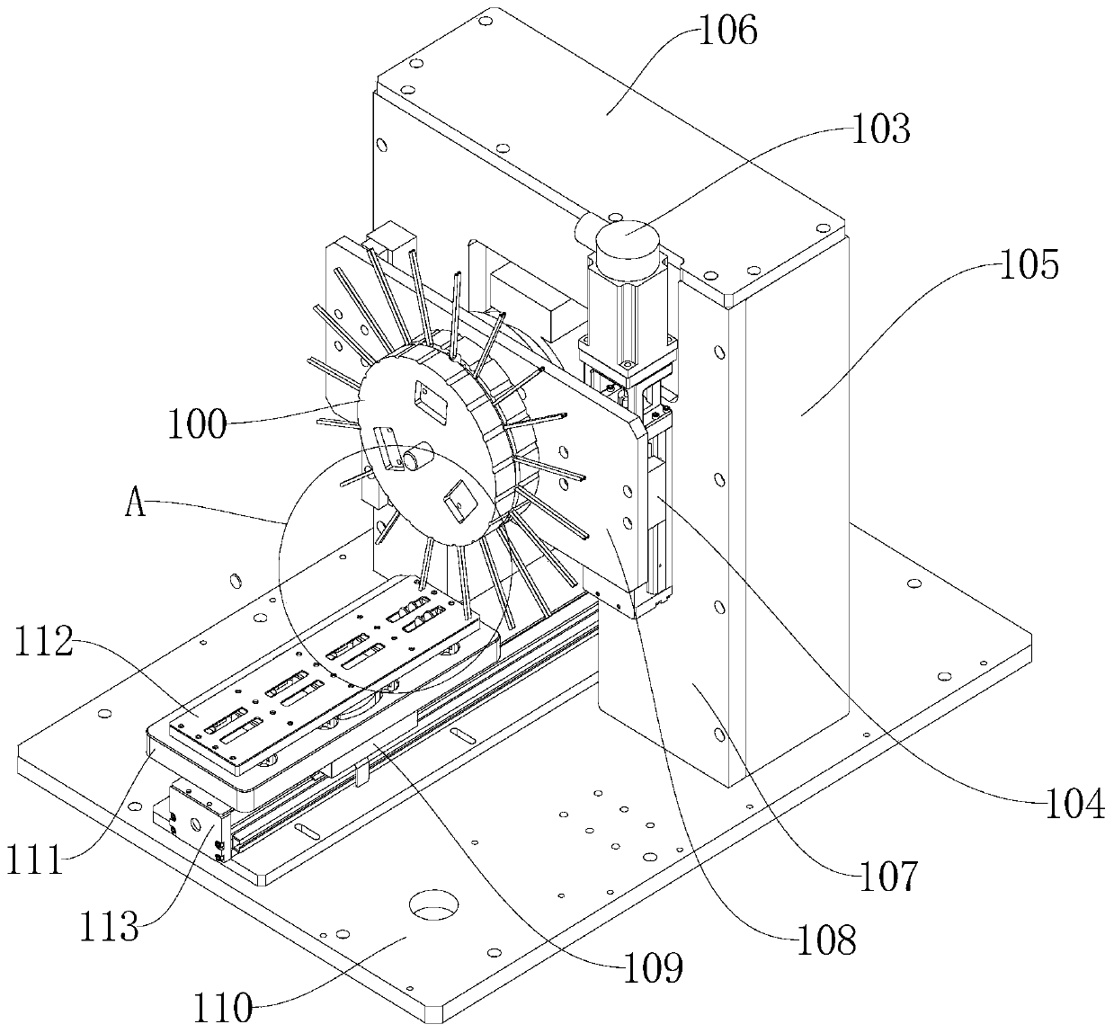
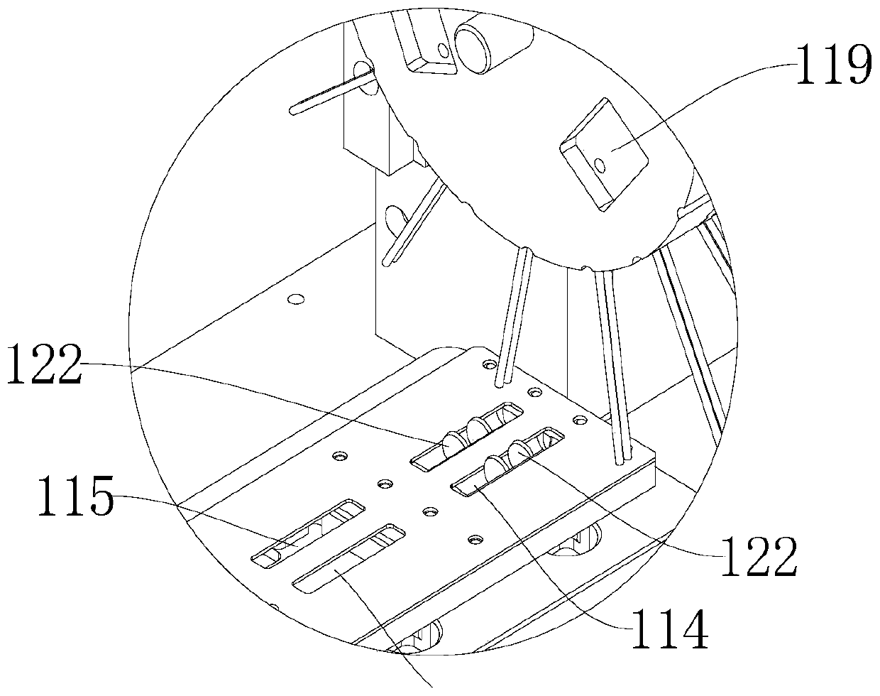
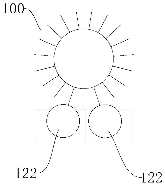
[0037] see Figure 1 to Figure 7 As shown, Embodiment 1 of the present invention provides a residual film removal device, including a polishing wheel 100, a power device, a lifting mechanism and a sliding mechanism; the power device is installed on the lifting mechanism, and the lifting mechanism can drive the polishing wheel 100 along the The lifting direction of the lifting mechanism moves, that is to say, the lifting mechanism drives the power unit and the polishing wheel 100 to move together along the lifting direction of the lifting mechanism; the sliding mechanism is used to drive the sheet product 122 to be removed to move along the sliding direction of the sliding mechanism; polishing The wheel disc 100 includes a disc body 101 and a plurality of glass fiber sleeves 102, and the plurality of glass fiber sleeves 102 are arranged at intervals in the circumferential direction of the disc body 101; the power device is used to drive the polishing wheel 100 to rotate, and thr...

Embodiment 2

[0053] see Figure 8 and Figure 9 As shown, Embodiment 2 of the present invention provides a system for removing residual film, including a system bracket and the device for removing residual film provided in Embodiment 1. The device for removing residual film is installed on the system bracket 127 . A control box 124 and a protective cover 125 are also installed on the system bracket; the control box is electrically connected to the first motor, the second motor 103 and the third motor respectively. The protective cover is used to prevent the glass fiber sleeve 102 on the polishing wheel 100 from being thrown off during the rotation of the polishing wheel 100 . Specifically, the installation base plate 110 is fixed on the system bracket; the control box is fixed on the installation base plate 110; a baffle plate 126 is installed on the protective cover, and the baffle plate can move up and down along the length direction of the slot on the protective cover. The baffle can ...


PUM


Abstract

The invention relates to the technical field of sapphire processing, in particular to a plastic film residue removing device and system. The plastic film residue removing device comprises a polishingwheel plate and a power device; the polishing wheel plate comprises a plate body and a plurality of glass fiber casing pipes which are distributed on the plate body at intervals in the circumferentialdirection; and the power device is used for driving the polishing wheel plate to rotate and polishing the edges of to-be-removed flaky products through the glass fiber casing pipes. The plastic filmresidue removing system comprises a system support and the plastic film residue removing device installed on the system support. By means of the plastic film residue removing device and system, the processing time can be greatly shortened, the labor intensity can be greatly relieved, and the production efficiency can be greatly improved.

Description

technical field [0001] The invention relates to the technical field of sapphire processing, in particular to a residual film removal device and a residual film removal system. Background technique [0002] Sapphire is a multifunctional oxide crystal integrating excellent optical, physical properties and stable chemical properties. The artificially grown sapphire has a hardness of up to 9 on the Mohs scale and very good wear resistance. There will be no marks when scratched by a hundred-grid knife with hardness. The dense crystal structure makes it have a large surface tension. [0003] Existing disc-shaped sapphire products need to be cured with a 0.01mm brittle thermosetting polymer material film on the surface, and a 0.1um functional metal oxide film is electroplated on the polymer material film. This kind of polymer material film and metal oxide film are extremely not resistant to scratches. In order to meet the appearance requirements of the product. It is necessary ...

Claims


Application Information

Patent Timeline
Patent Type & Authority Patents(China)
IPC IPC(8): B24B27/033B24B41/00B24B55/06
CPCB24B27/033B24B41/00B24B55/06
Inventor 周群飞饶桥兵蒋珊汶
Owner LENS TECH CHANGSHA
Learn More