

Polymer foaming device and method for polymer foaming through polymer foaming device
A foaming device and polymer technology, which is applied in the field of polymer foaming equipment and polymer foaming devices, can solve the problems of heating dead angle, high heating temperature, and small foaming ratio, so as to improve the heating speed and broad application prospects , Fast and efficient foaming effect
- Summary
- Abstract
- Description
- Claims
- Application Information
AI Technical Summary
Problems solved by technology
Method used
Image

Examples
Embodiment 1
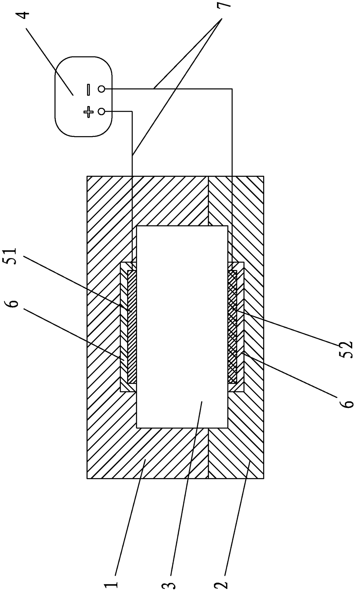
[0048] Such as figure 1 As shown, the polymer foaming device of the present invention includes a mold, a radio frequency power supply 4, a first radio frequency electrode 51 and a second radio frequency electrode 52, the mold has a mold cavity 3, and the cavity wall of the mold cavity 3 is opened There are pits for installing the first radio frequency electrode 51 and the second radio frequency electrode 52, the first radio frequency electrode 51 and the second radio frequency electrode 52 are respectively embedded in the pits, so The first radio frequency electrode 51, the second radio frequency electrode 52 and the inner surface of the pit are separated by an electrical insulating interlayer 6 between the first radio frequency electrode 51, the second radio frequency electrode 52 and the pit contact surface. and ensure that at least one side of the first radio frequency electrode 51 and the second radio frequency electrode 52 is exposed in the airtight cavity 3; the first ra...
Embodiment 2
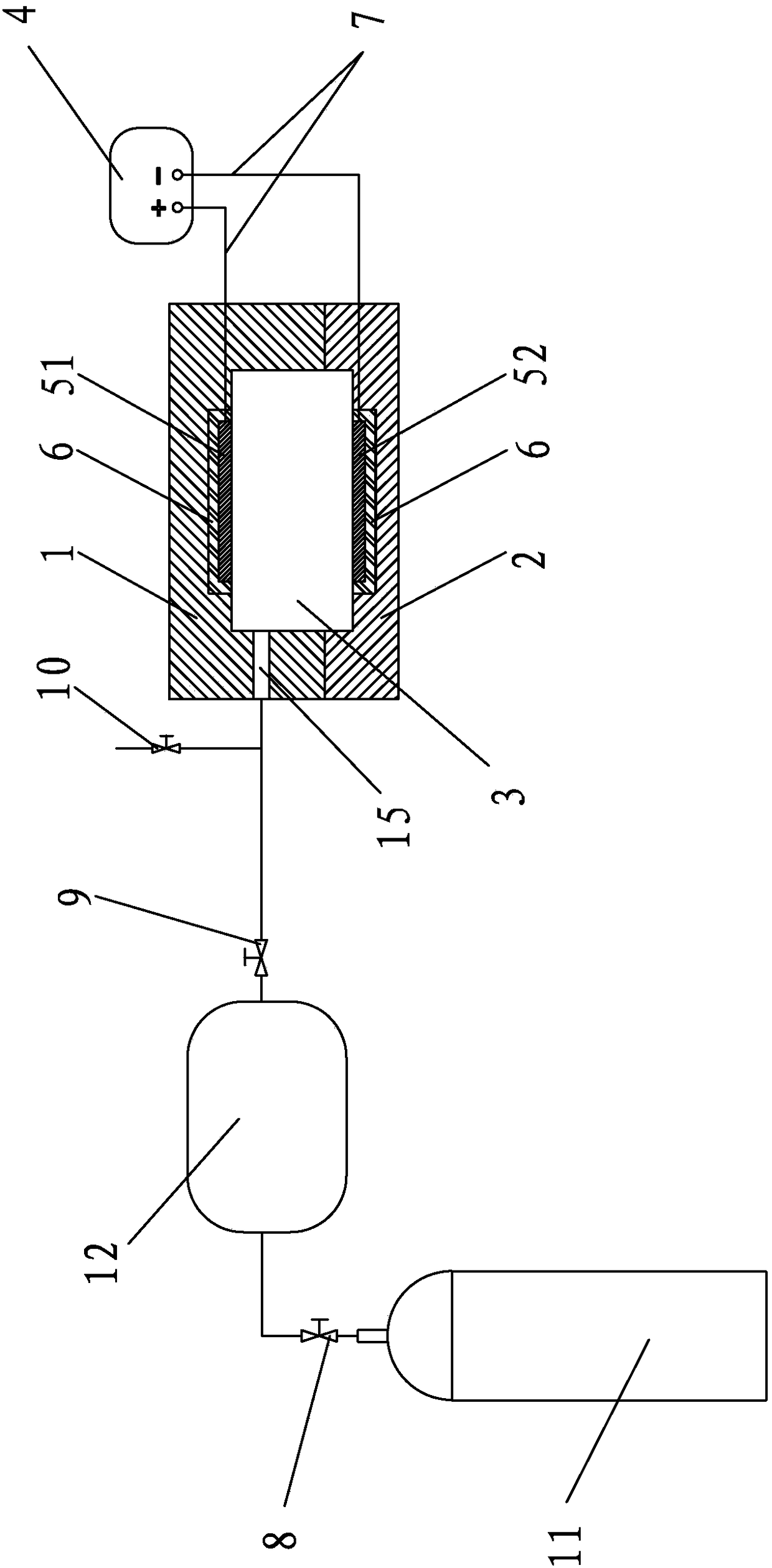
[0059] Such as figure 2 As shown, the polymer foaming device of the present invention includes a mold, a radio frequency power supply 4, a first radio frequency electrode 51 and a second radio frequency electrode 52, the mold has a mold cavity 3, and the cavity wall of the mold cavity 3 is opened There are pits for installing the first radio frequency electrode 51 and the second radio frequency electrode 52, the first radio frequency electrode 51 and the second radio frequency electrode 52 are respectively embedded in the pits, the first radio frequency electrode 51 and the second radio frequency electrode 52 are embedded in the pits respectively, A radio-frequency electrode 51, the second radio-frequency electrode 52 and the contact surface of the pit are compounded with an electromagnetic wave shielding material layer and an electrical insulating material layer to form an interlayer 6. The first radio-frequency electrode 51, the second radio-frequency electrode 52 and the T...
Embodiment 3
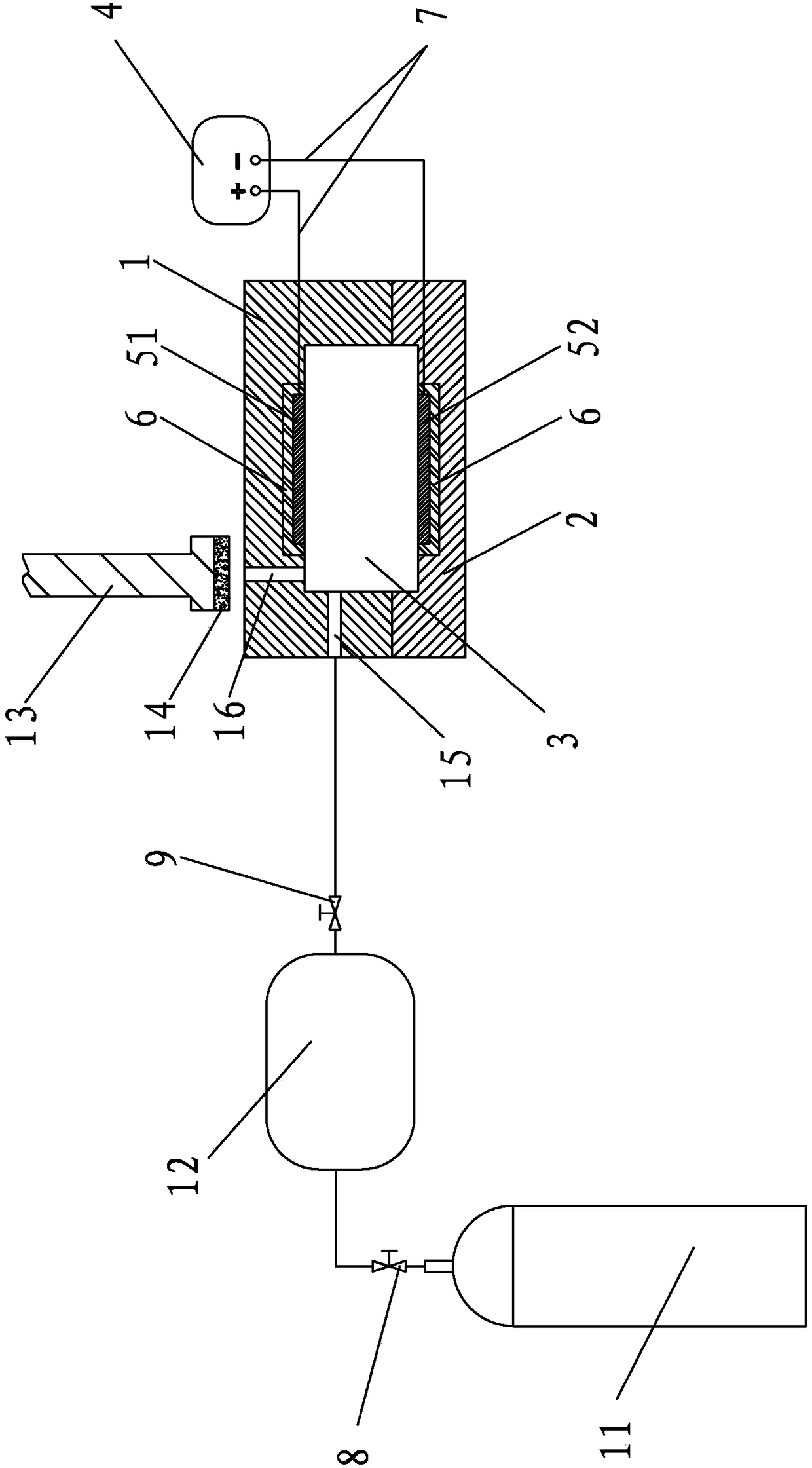
[0072] Such as image 3As shown, the polymer supercritical foaming device of the present invention includes a mould, a radio frequency power supply 4, a first radio frequency electrode 51 and a second radio frequency electrode 52, the mold has a mold cavity 3, and the cavity wall of the mold cavity 3 There are pits for installing the first radio frequency electrode 51 and the second radio frequency electrode 52, and the first radio frequency electrode 51 and the second radio frequency electrode 52 are respectively embedded in the pits. , between the first radio frequency electrode 51, the second radio frequency electrode 52 and the contact surface of the pit, the first radio frequency electrode 51, the second radio frequency electrode 52 are separated from the inner surface of the pit by an electrically insulating interlayer 6, And ensure that at least one side of the first radio frequency electrode 51 and the second radio frequency electrode 52 is exposed in the airtight mold...
PUM
| Property | Measurement | Unit |
|---|---|---|
| Hardness | aaaaa | aaaaa |
Abstract
Description
Claims
Application Information