Polyurethane foaming system

A foaming system and polyurethane technology, applied in the field of polyurethane foaming systems, can solve the problems of unstable foaming, blockage of discharge pipes, restrictions, etc., and achieve the effects of improving stirring efficiency, increasing force area, and improving foaming efficiency

Active Publication Date: 2018-06-29
于泽
View PDF4 Cites 8 Cited by
  • Summary
  • Abstract
  • Description
  • Claims
  • Application Information

AI Technical Summary

Problems solved by technology

The above-mentioned machine tool is equipped with a product foaming chamber at the bottom of the bed, and a rolling chain-belt conveying mechanism is installed on the bottom of the foaming chamber to cast polyurethane sealing strip products. After the products enter the F front inlet of the temperature-controlled foaming chamber, the products Under the control and conveying speed adjustment, it can be foamed and shaped quickly within a certain period of time, and the foamed product is sent from the rear outlet. Although this technical solution can realize foaming of polyurethane sealing strips, this technical solution can only To solve the problem of the blockage of the discharge pipe, for the process reasons such as the foaming instability in the existing polyurethane production, it is impossible to improve the equipment to make up for the lack of technology, so that the invention is limited

Method used


Image

  • Polyurethane foaming system
  • Polyurethane foaming system
  • Polyurethane foaming system

Examples


Embodiment approach

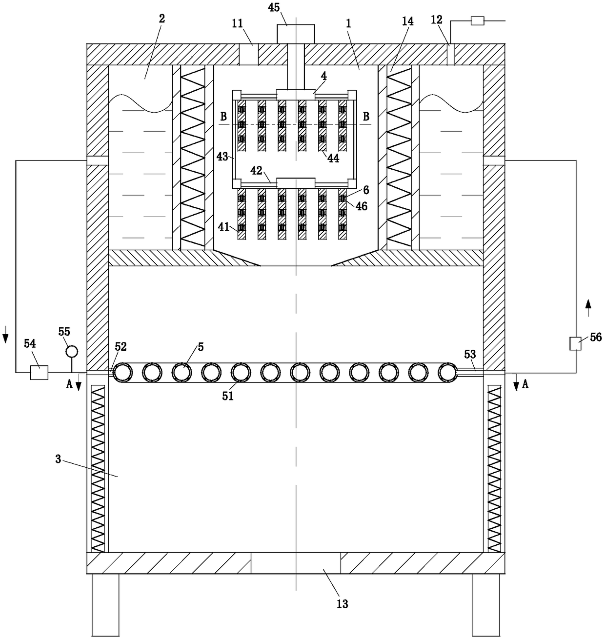
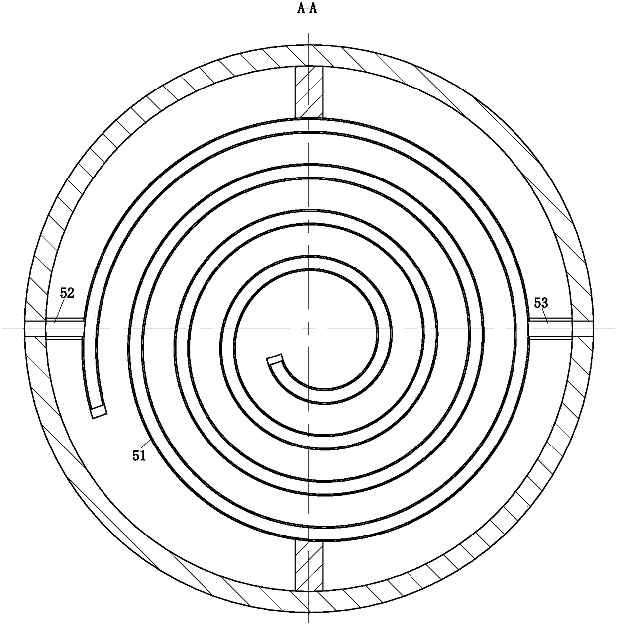
[0027] As an embodiment of the present invention, the water control unit 5 includes a spiral pipe 51, a No. 1 liquid inlet pipe 52, a No. 1 liquid outlet pipe 53, a No. 1 solenoid valve 54, a No. 1 hydraulic gauge 55 and a No. 2 solenoid valve. 56; the spiral tube 51 is fixedly installed on the inner wall of the No. 1 side plate through a bracket; the left end of the spiral tube 51 is connected to the water storage tank 2 through the No. 1 liquid inlet pipe 52, the No. 1 hydraulic gauge 55, and the No. 1 solenoid valve 54 Connected, the right side of the spiral tube 51 is connected with the water storage bin 2 through the No. 1 liquid outlet pipe 53 and the No. 2 solenoid valve 56; The spray holes evenly cover the surface of the spiral tube 51, and the apertures of the spray holes are relatively small. When the first solenoid valve 54 and the second solenoid valve 56 were all opened, the water in the spiral tube 51 could not be ejected from the spray holes. When No. 1 solenoid...


PUM


Abstract

The invention belongs to the technical field of polyurethane production equipment and particularly discloses a polyurethane foaming system. The polyurethane foaming system comprises a dual stirring unit and a water control unit, wherein a heating cylinder is fixedly mounted on the upper surface of an upper bottom plate II; a stirring bin is located in the heating cylinder; a water storage bin is located between the outer wall of the heating cylinder and a side plate I; a foaming bin is located between the upper bottom plate II and a lower bottom plate I; the dual stirring unit is located in the stirring bin; the water control unit is located in the foaming bin; a spiral plate I is fixedly mounted at the lower end of a connection rod I through a mounting rack I; the upper end of the connection rod I is fixedly connected with a mounting rack II; a spiral plate II is fixedly mounted on the lower surface of the mounting rack II. The invention discloses a processing method of dual stirringtype polyurethane heat insulation boards. The polyurethane foaming system is mainly used for producing the polyurethane heat insulation boards and is capable of rapidly and uniformly mixing the raw materials, accelerating the melting of the raw materials and improving the foaming quality of the raw materials.

Description

technical field [0001] The invention belongs to the technical field of polyurethane production equipment, in particular to a polyurethane foaming system. Background technique [0002] With the tight housing area of ​​modern families, there is an increasingly strong demand for thin-walled household refrigerator products. In the manufacturing process of refrigerator thin-walled products, due to the thinning of the refrigerator wall, the thermal insulation performance and mechanical strength of the foam layer are deteriorated, and the flow of foaming raw materials at the corners with complex structures is insufficient, resulting in false filling. . At present, the cyclopentane foaming system widely used in refrigerators cannot meet the technical requirements of thin-walled products. Therefore, it is imperative to develop a foaming system with high fluidity, high heat retention and high strength. In the field, the uniformity of stirring raw materials and the adequacy of contac...

Claims


Application Information

Patent Timeline
Patent Type & Authority Applications(China)
IPC IPC(8): B29C44/34B29K75/00
CPCB29C44/3442B29C44/35B29K2075/00
Inventor 王慧丽孙勇丁宝林
Owner 于泽
Why Eureka
Try Eureka