

Foam generation device for toilet bowl
A foam generating device and toilet technology, applied in water supply devices, sanitary equipment for toilets, buildings, etc., can solve the problems of poor gas-water mixing effect, waste, poor mixing effect, etc., and achieve quality gradient reduction, fine foam, and speed. The effect of gradient reduction
- Summary
- Abstract
- Description
- Claims
- Application Information
AI Technical Summary
Problems solved by technology
Method used
Image

Examples
no. 1 example
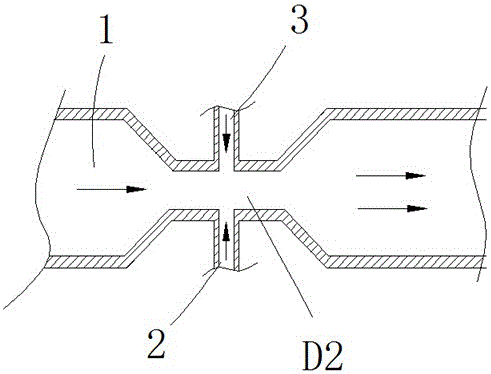
[0042] A foam generating device for a toilet, comprising a water inlet pipeline 1, an air inlet pipeline 2, a foaming agent pipeline 3, and a mixer 4 connected to the end of the pipeline for fully mixing water, air, and foaming agent to generate foam , the end of the mixer 4 is connected to the foam pipe 5, the mixer 4 includes at least one static mixing unit, and a plurality of continuously twisted fins are arranged in the static mixing unit, so that the liquid entering the mixer 4 constantly changes the flow direction, realizing air and liquid Blend to create a fine foam.
[0043] In the embodiment, a constant pressure valve capable of maintaining a stable water pressure is installed on the water inlet line 1, and a pressure regulating switch is installed on the air intake line 2 to keep the intake pressure constant.
[0044] In an embodiment, in the gas-water mixture, the ratio of gas to water ranges from 1:1 to 10:1.
[0045] In an embodiment, the dispersion degree of the...
no. 2 example
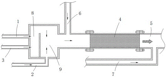
[0049] The second embodiment: as image 3 and Figure 4 as shown,
[0050] In the embodiment, the front end of the mixer is provided with a water inlet branch 6 capable of regularly cleaning the mixer 4 , and the water inlet branch 6 is provided with a solenoid valve for opening and closing the water inlet branch 6 .
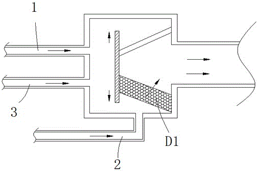
[0051] In the embodiment, the water inlet pipeline 1 and the foaming agent pipeline 3 are mixed through the first pre-mixing device 8 to form a dilute foaming agent solution with a low viscosity, and the dilute solution is then passed through the second pre-mixing device with the air in the air intake pipeline 2. The mixing device 9 mixes to form the gas-water mixture, and then enters the mixer 4 .
[0052] In the embodiment, before the foam generating device for the toilet finishes foaming once, the air inlet pipeline 2 and the foaming agent pipeline 3 stop conveying gas and foaming agent, and only the water inlet pipeline 1 operates, and the water flows thro...
no. 3 example
[0056] The third embodiment: as Figure 5 and Figure 6 as shown,
[0057] In this embodiment, on the basis of the second embodiment, the water flow delivery pipe 7 connected from below the end outlet of the mixer 4 is set as the water flow delivery pipe 7 connected tangentially from the end outlet of the mixer 4, and the water flow delivery The water flow that the pipe 7 rushes out advances in a spiral shape, and the foam is taken out quickly. This way of flushing out the foam makes the water flow and the foam mix more evenly.
PUM
 Abstract
Description
Claims
Application Information