Screw feeding device directly driven by frameless type permanent magnet synchronous motor

A permanent magnet synchronous motor, screw feeding technology, applied in the field of machinery, can solve the problems of poor geological adaptability, affecting the use of the motor, unable to continuously adjust the speed, etc., to achieve the effect of fast response, accelerated heat dissipation, and flexible selection.

Pending Publication Date: 2018-06-29
HUBEI HUANYEE ELECTROMAGNETIC EQUIP ENG TECH CO LTD
View PDF11 Cites 0 Cited by
  • Summary
  • Abstract
  • Description
  • Claims
  • Application Information

AI Technical Summary

Problems solved by technology

[0005] The current screw feeding devices currently on the market are dusty and noisy during use, which affects the use of the motor; in addition, most screw feeding devices currently use a combination of two-speed motor main drive and hydraulic motor auxiliary drive mode or variable frequency motor Drive mode, there are problems such as continuous speed regulation and poor geological adaptability

Method used


Image

  • Screw feeding device directly driven by frameless type permanent magnet synchronous motor
  • Screw feeding device directly driven by frameless type permanent magnet synchronous motor
  • Screw feeding device directly driven by frameless type permanent magnet synchronous motor

Examples


Embodiment 1

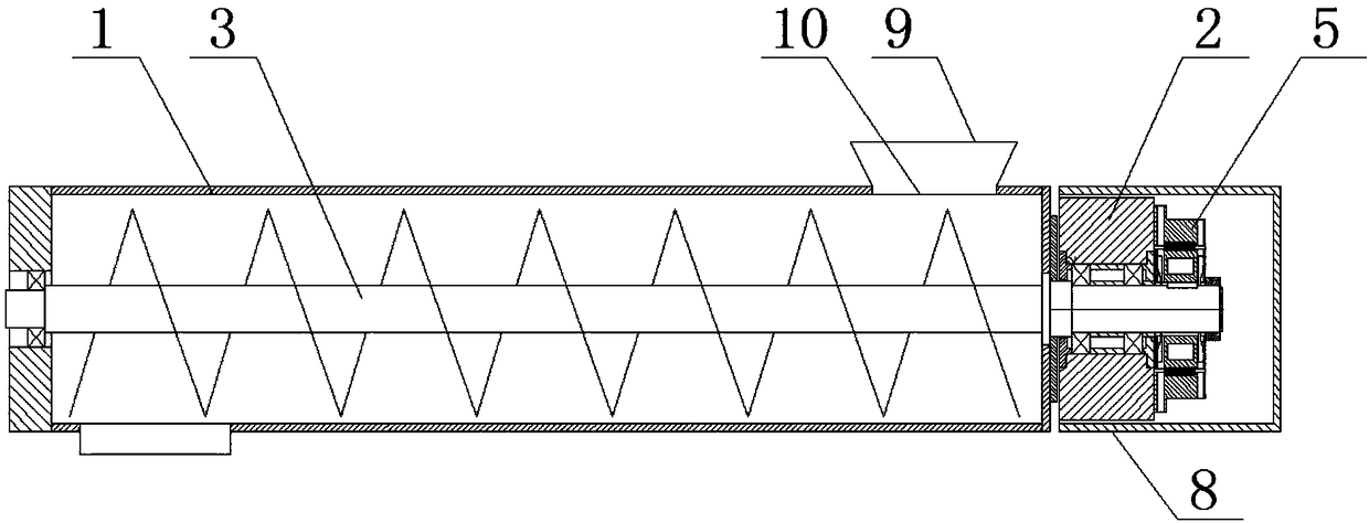
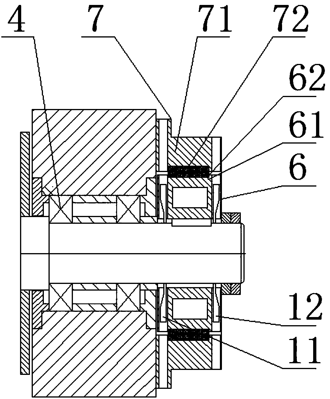
[0033] like figure 1 , 2As shown, this embodiment provides a screw feeding device directly driven by a frameless permanent magnet synchronous motor, including a frame 2, a feeding chamber 1 installed on the frame 2, a screw shaft 3, a bearing 4, and a The screw blade on the screw shaft 3 and the frameless permanent magnet synchronous motor 5, the screw shaft 3 runs through the feeding chamber 1, and is installed on the frame 2 through the bearing 4, the screw shaft 3 Rotationally connected with the feeding chamber 1; the screw shaft 3 is directly driven by the frameless permanent magnet synchronous motor 5; the frameless permanent magnet synchronous motor 5 includes a stator assembly 7 and a rotor assembly 6; the stator The assembly 7 is fixedly installed on the frame 2 to provide a rotating magnetic field for the rotor assembly 6; the rotor assembly 6 with permanent magnet properties is fixedly installed on the screw shaft 3,

[0034] Wherein, the stator assembly 7 includes...

Embodiment 2

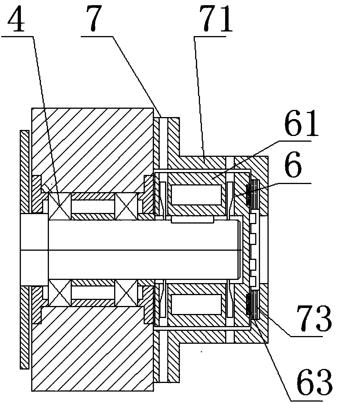
[0038] Such as image 3 As shown, this embodiment provides a screw feeding device directly driven by a frameless permanent magnet synchronous motor. Compared with Embodiment 1, the difference is that the stator assembly 7 includes a disc-shaped stator core 73 and a winding The stator winding on the disc-shaped stator core 73, the disc-shaped stator core 73 is integrally processed into an annular disc-shaped structure; sieve 10.

[0039] As a preference of this embodiment, the rotor assembly 6 includes a rotor base 61 and a disc-shaped magnetic steel base plate 63, the rotor base 61 is fixedly mounted on the screw shaft 3, and the disc-shaped magnetic steel base plate 63 wraps around The center line of the screw shaft 3 is evenly distributed on the rotor base 61; the end of the screw shaft 3 is a cylindrical structure; the rotor base 61 is an annular column with a sealing plate on one end; the rotor The base 61 is fixedly installed on the end of the screw shaft 3; the disc-sh...

Embodiment 3

[0042] Such as Figure 4 As shown, this embodiment provides a screw feeding device directly driven by a frameless permanent magnet synchronous motor. Compared with Embodiment 1, the difference is that the stator assembly 7 includes an arc-shaped stator core 72 and a disc shaped stator core 73, the arc-shaped stator core 72 and the disc-shaped stator core 73 are wound with stator windings; 73 is integrally processed into an annular disk-shaped structure.

[0043] As a preference of this embodiment, the rotor assembly 6 includes a rotor base 61, an arc-shaped magnetic steel base plate 62 and a disc-shaped magnetic steel base plate 63, the rotor base 61 is fixedly mounted on the screw shaft 3, and the The arc-shaped magnetic steel base plate 62 and the disc-shaped magnetic steel base plate 63 are evenly distributed on the rotor base 61 around the axis center line of the screw shaft 3; the end of the screw shaft 3 has a cylindrical structure; the rotor base 61 It is an annular c...


PUM


Abstract

The invention discloses a screw feeding device directly driven by a frameless type permanent magnet synchronous motor. The screw feeding device directly driven by the frameless type permanent magnet synchronous motor comprises a rack, a feeding cavity, a screw shaft, a bearing, spiral blades and the frameless type permanent magnet synchronous motor, wherein the rack is provided with the feeding cavity, the screw shaft and the bearing, and the spiral blades are installed on the screw shaft; the frameless type permanent magnet synchronous motor comprises a stator assembly and a rotor assembly; the stator assembly is fixedly installed on the rack, and provides a rotating magnetic filed for the rotor assembly; the rotor assembly with the permanent magnet characteristic is fixedly installed onthe screw shaft; the stator assembly comprises a stator iron core and a stator winding wound on the stator iron core; the stator iron core is integrally machined and formed or is an annular column oran annular disk formed by splicing a plurality of sector-shaped blocks. According to the screw feeding device directly driven by the frameless type permanent magnet synchronous motor, the screw shaftis driven by the frameless type permanent magnet synchronous motor to rotate, and the beneficial effects that the transmission efficiency is high, noise is low and torque is large are achieved.

Description

technical field [0001] The invention belongs to the technical field of machinery, and in particular relates to a screw feeding device directly driven by a frameless permanent magnet synchronous motor. Background technique [0002] Screw feeding is a kind of continuous conveying equipment without disturbing traction components. It uses the rotating screw to push the conveyed material along the surface of the fixed casing for conveying work. Its situation is like being held by a nut that cannot rotate. Like the translational movement along the screw rod, the force that keeps the material from rotating with the screw is the gravity of the material and the frictional resistance of the casing on the material. Screw feeders have been widely used in various industrial sectors, such as building materials, electric power, chemical industry, metallurgy, coal mining, machinery, grain and food industries, etc. [0003] Chinese patent CN206842362U discloses a premixed powder screw feedi...

Claims


Application Information

Patent Timeline
Patent Type & Authority Applications(China)
IPC IPC(8): B65G33/14B65G33/24B65G33/32B65G33/34H02K1/20H02K5/10H02K7/14H02K9/06H02K9/22
CPCH02K1/20H02K5/10H02K7/14H02K9/06H02K9/22B65G33/14B65G33/24B65G33/32B65G33/34
Inventor 黄诚杨勇强
Owner HUBEI HUANYEE ELECTROMAGNETIC EQUIP ENG TECH CO LTD
Why Eureka
Try Eureka