High-temperature rapid shaping annealing furnace for ultrathin photovoltaic glass

A photovoltaic glass, high temperature and fast technology, applied in the field of photovoltaic glass forming section, can solve the problems of glass bending, annealing, inability to convey, and achieve the effect of preventing bending deformation and bursting, good flatness, and improving production efficiency

Inactive Publication Date: 2018-06-29
CNBM YIXING NEW ENERGY CO LTD
View PDF6 Cites 6 Cited by
  • Summary
  • Abstract
  • Description
  • Claims
  • Application Information

AI Technical Summary

Problems solved by technology

The use of traditional annealing furnaces can no longer meet the needs of ultra-thin glass forming annealing
[0004] Since the thickness of the ultra-thin photovoltaic glass is only 1.5mm to 2.0mm, the distance between the conveying rollers in zone A of the traditional annealing kiln is 250mm, and the state of the ultra-thin glass plate drawn from the calender is extremely unstable at this time. It will lead to poor or even impossible conveying of the glass ribbon; affected by gravity, the glass between the rollers will sag and bend; the traditional annealing furnace does not have a heating temperature control device, and the glass ribbon plane stress and transverse temperature difference are too large, resulting in glass bursting
Therefore, the traditional annealing furnace cannot transport and anneal the glass ribbon, and cannot meet the needs of ultra-thin glass production.

Method used


Image

  • High-temperature rapid shaping annealing furnace for ultrathin photovoltaic glass
  • High-temperature rapid shaping annealing furnace for ultrathin photovoltaic glass

Examples


Embodiment 1

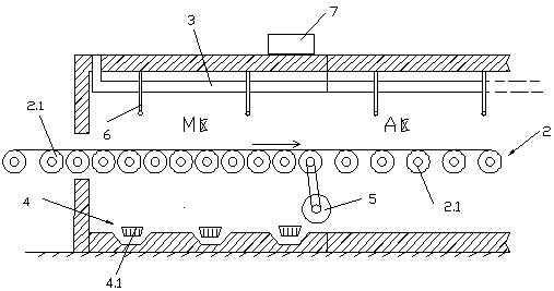
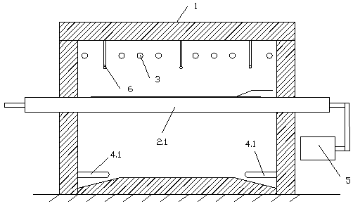
[0024] Example 1: A high-temperature rapid prototyping annealing kiln for ultra-thin photovoltaic glass, including a kiln body 1, A, B, C, D, RET, and F temperature zones sequentially arranged in the kiln body 1, and the kiln body 1 starts from the entrance From the material end to the discharge end, a conveying roller table 2 is provided. The conveying roller table 2 includes several conveying rollers 2.1 arranged side by side and a motor that drives the conveying rollers 2.1 to run. A cooling air duct 3 is arranged near the top of the kiln body 1. A heating device 4 is installed near the bottom of the kiln body 1, and an M area is added in front of the A area, and the density of the conveying rollers 2.1 located in the M area is greater than that of the conveying rollers 2.1 in the A, B, C, D, RET, and F temperature areas. Density, the conveying roller 2.1 located in the M area is separately driven by an adjustable speed motor 5, and the temperature measuring thermocouple 6 i...


PUM

PropertyMeasurementUnit
thicknessaaaaaaaaaa
thicknessaaaaaaaaaa

Abstract

The invention discloses a high-temperature rapid shaping annealing furnace for ultrathin photovoltaic glass. The high-temperature rapid shaping annealing furnace comprises a furnace body, an A warm area, a B warm area, a C warm area, a D warm area, an RET warm area and an F warm area, wherein the A warm area, the B warm area, the C warm area, the D warm area, the RET warm area and the F warm areaare sequentially arranged in the furnace body; a conveying roller way is arranged on the furnace body in a penetrating mode from a feeding end to a discharging end; the conveying roller way comprisesa plurality of conveying rollers which are distributed in parallel and a motor for driving the conveying roller to rotate, a cooling air tube is arranged in the furnace body and close to the top end of the furnace body, and a heating device is arranged in the furnace body and close to the bottom end of the furnace body; an M area is additionally arranged in front of the A area, and the conveying roller density in the M area is larger than that of the A warm area, the B warm area, the C warm area, the D warm area, the RET warm area and the F warm area; conveying rollers in the M area are independently provided with speed-adjustable motors to be driven, a temperature thermocouple is arranged in the M area, a heating device in the M area is an adjustable type heating device, the temperature thermocouple is electrically connected with a temperature control system, and the temperature thermocouple is in signal connection with the adjustable heating device.

Description

technical field [0001] The invention relates to a forming section of photovoltaic glass, in particular to an annealing kiln for high-temperature rapid forming of ultra-thin photovoltaic glass. Background technique [0002] The traditional photovoltaic glass annealing kiln is divided into A, B, C, D, RET, and F temperature zones, suitable for annealing photovoltaic glass with a thickness of 2.5mm~4.0mm. By adjusting the electric heating and air-cooling systems in each temperature zone, the temperature of the glass ribbon in each temperature zone is close to the set temperature of the temperature zone, so that the stress of the glass ribbon in the temperature zone changes uniformly and the integrity of the glass ribbon is guaranteed. [0003] Ultra-thin photovoltaic glass is an ultra-white glass with a glass thickness of 1.5mm~2.0mm in response to the market's ultra-thin and high-permeability requirements. The forming technology of ultra-thin glass is high temperature rapid p...

Claims


Application Information

Patent Timeline
Patent Type & Authority Applications(China)
IPC IPC(8): C03B25/08
CPCC03B25/08
Inventor 李茂刚曾敏李镇罗二成
Owner CNBM YIXING NEW ENERGY CO LTD
Why Eureka
Try Eureka