Improved construction device for road repairing

A technology of road repair and construction device, applied in the direction of road repair, roads, roads, etc., can solve the problems of low construction efficiency, slow construction speed, large floor space, etc., and achieve the effect of convenient operation and simple structure

Inactive Publication Date: 2018-06-29
广州曙迅自动化设备有限公司
View PDF3 Cites 2 Cited by
  • Summary
  • Abstract
  • Description
  • Claims
  • Application Information

AI Technical Summary

Problems solved by technology

[0002] In some construction sites, such as road construction, it is necessary to carry out broken repairs on roads that have been used for too long to cause pits and partial collapse. At present, roads need to be intercepted during repair construction, and large engineering vehicles are used to cut open the damaged road surface , and then fill the asphalt after cleaning. As we all know, the cost of large-scale engineering vehicles is very high, which undoubtedly greatly increases the maintenance cost for the daily maintenance of the road, and the construction speed is extremely slow, and the floor space is large. The existing road construction device has a complex structure, poor crushing effect, large potential safety hazards in the exposed transmission mechanism, and low construction efficiency. In view of the above defects, it is necessary to design an improved construction device for road repair.

Method used


Image

  • Improved construction device for road repairing
  • Improved construction device for road repairing
  • Improved construction device for road repairing

Examples


Embodiment Construction

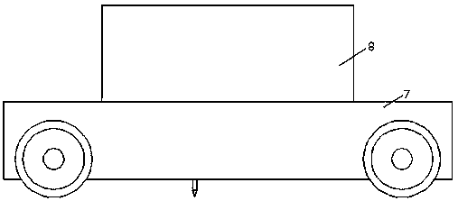
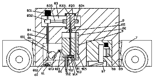
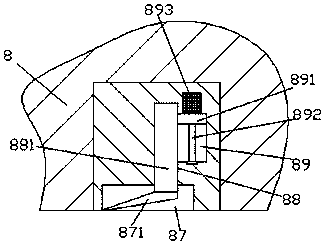
[0013] Such as figure 1 , figure 2 with image 3 As shown, an improved construction device for road repair of the present invention includes a loading vehicle body 7 and a construction machine body 8 fixedly installed in the loading vehicle body 7, and a transmission chamber 81 is provided inside the construction machine body 8. The right end of the transmission chamber 81 is communicated with a guide chamber 82 extending upward, and the inner wall of the construction body 8 on the upper side of the guide chamber 82 is provided with a drive chamber 83 extending to the left. The left extension section of the driving chamber 83 is located in the construction machine body 8 above the top of the transmission chamber 81, and the inner wall of the construction machine body 8 between the transmission chamber 81 and the drive chamber 83 is provided with a first passageway. Hole 84, the first through hole 84 is transitionally connected with a rotating shaft 841 extending up and down...


PUM


Abstract

The invention discloses an improved construction device for road repairing. The improved construction device comprises a loading vehicle body and a construction machine body, wherein the constructionmachine body is fixedly arranged in the loading vehicle body; a transmission cavity is formed in the construction machine body; the tail end of the right side of the transmission cavity is communicated with a sliding guiding cavity stretching upwards; a driving cavity stretching leftwards is formed in an inner wall body of the construction machine body arranged at the upper side of the sliding guiding cavity; a stretching section of the left side of the driving cavity is located in the construction machine body above the top part of the transmission cavity; a first through hole is formed in the inner wall body of the construction machine body between the transmission cavity and the driving cavity in a penetrating way; the first through hole is internally in transition fit connection with arotating shaft stretching up and down; a stretching section of the top part of the rotating shaft stretches into the driving cavity, and a stretching tail end is in power fit connection with a firstmotor; the outer surface of the first motor is embedded in and fixedly connected with the inner top wall of the driving cavity; a stretching tail end of the bottom part of the rotating shaft stretchesinto the transmission cavity and is in rotational fit connection with the inner bottom wall of the transmission cavity. The improved construction device disclosed by the invention is simple in structure, convenient to operate and high in safety, and the crushing speed and the crushing quality are increased.

Description

technical field [0001] The invention relates to the technical field of road construction, in particular to an improved construction device for road repair. Background technique [0002] In some construction sites, such as road construction, it is necessary to carry out broken repairs on roads that have been used for too long to cause pits and partial collapse. At present, roads need to be intercepted during repair construction, and large engineering vehicles are used to cut open the damaged road surface , and then fill the asphalt after cleaning. As we all know, the cost of large-scale engineering vehicles is very high, which undoubtedly greatly increases the maintenance cost for the daily maintenance of the road, and the construction speed is extremely slow, and the floor space is large. The existing road construction device has a complex structure, poor crushing effect, large potential safety hazards in the exposed transmission mechanism, and low construction efficiency. I...

Claims


Application Information

Patent Timeline
Patent Type & Authority Applications(China)
IPC IPC(8): E01C23/12
CPCE01C23/124
Inventor 时建华
Owner 广州曙迅自动化设备有限公司
Why Eureka
Try Eureka