
A new heat recovery structure

A new type of hot end technology, applied in the field of new heat recovery structure, can solve the problems of large cold end of Stirling motor, increased heat leakage area, and increased shell volume, so as to ensure smoothness and reduce heat leakage area, performance-enhancing effects

Active Publication Date: 2020-05-22
CHINA STIRLING ENGINE MFG
View PDF4 Cites 0 Cited by
  • Summary
  • Abstract
  • Description
  • Claims
  • Application Information

AI Technical Summary

Problems solved by technology

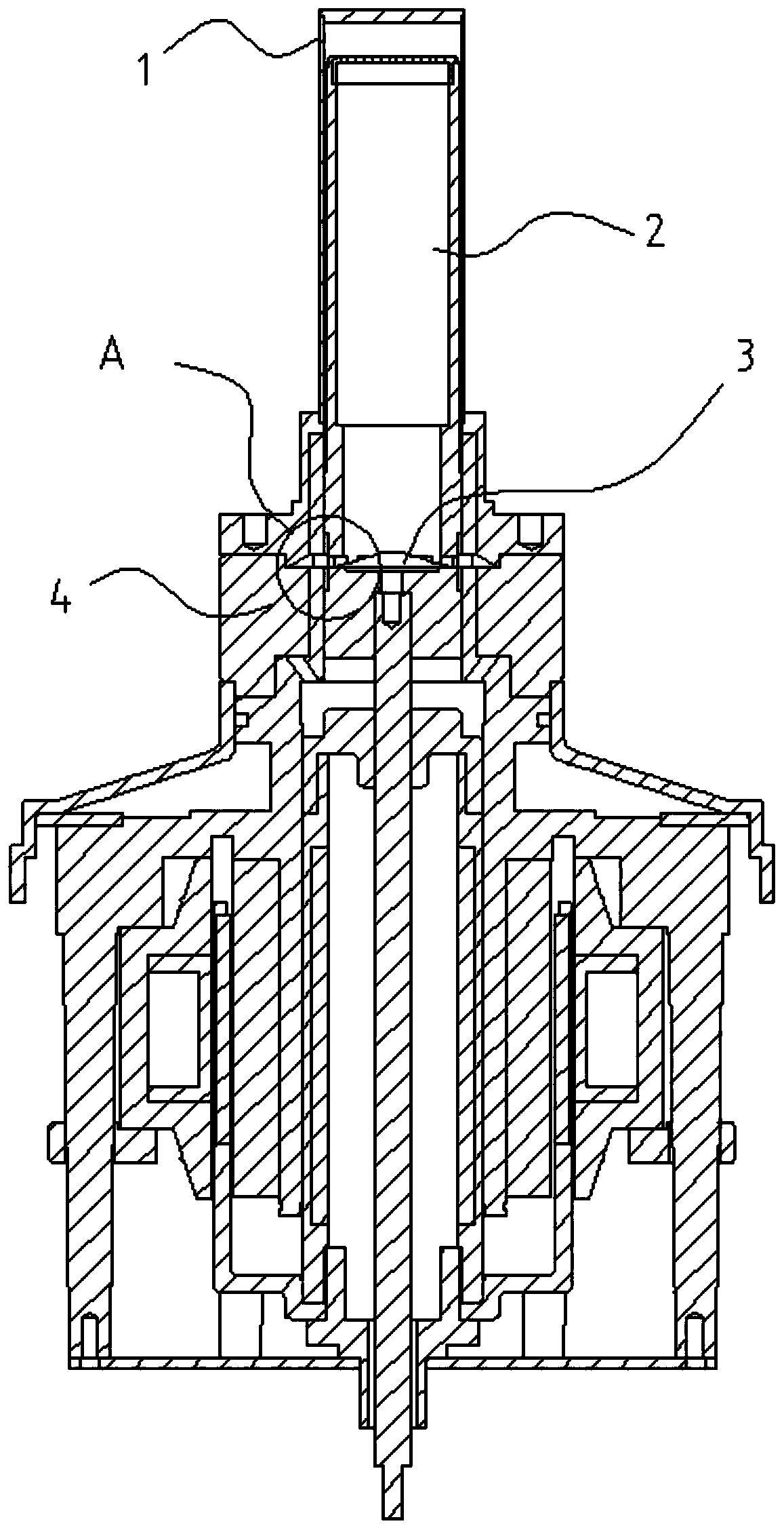
[0003] At present, the heat recovery structure of Stirling motors on the market includes a heat sink at the hot end and a heat sink at the cold end, and a regenerator is arranged between the heat sink at the hot end and the heat sink at the cold end, and the heat sink at the hot end and the heat sink at the cold end The heat sink and the regenerator are ring-shaped and sleeved on the passage of the piston movement, so that the gas can continuously pass between the heat sink at the hot end, the regenerator and the radiator at the cold end under the action of the piston to release energy. , this heat recovery structure is set between the cold end and the hot end of the Stirling motor, and is also sleeved outside the piston, resulting in a larger volume of the cold end and part of the hot end of the Stirling motor, resulting in a larger shell volume Increase, increase the heat leakage area, at the same time, the piston of the current heat recovery structure is hollow, the heat will be conducted through the hollow inside the piston, which will also increase the heat leakage area, and the cold end of the shell is due to the piston Due to the structure of the cold end, the piston cannot fully reach the top of the cold end and fit on the top surface of the cold end, resulting in a partial dead volume, and the air in the dead volume does not do work. These factors have a great impact on the performance of the Stirling motor

Method used


Image

  • A new heat recovery structure
  • A new heat recovery structure
  • A new heat recovery structure

Examples


Embodiment Construction

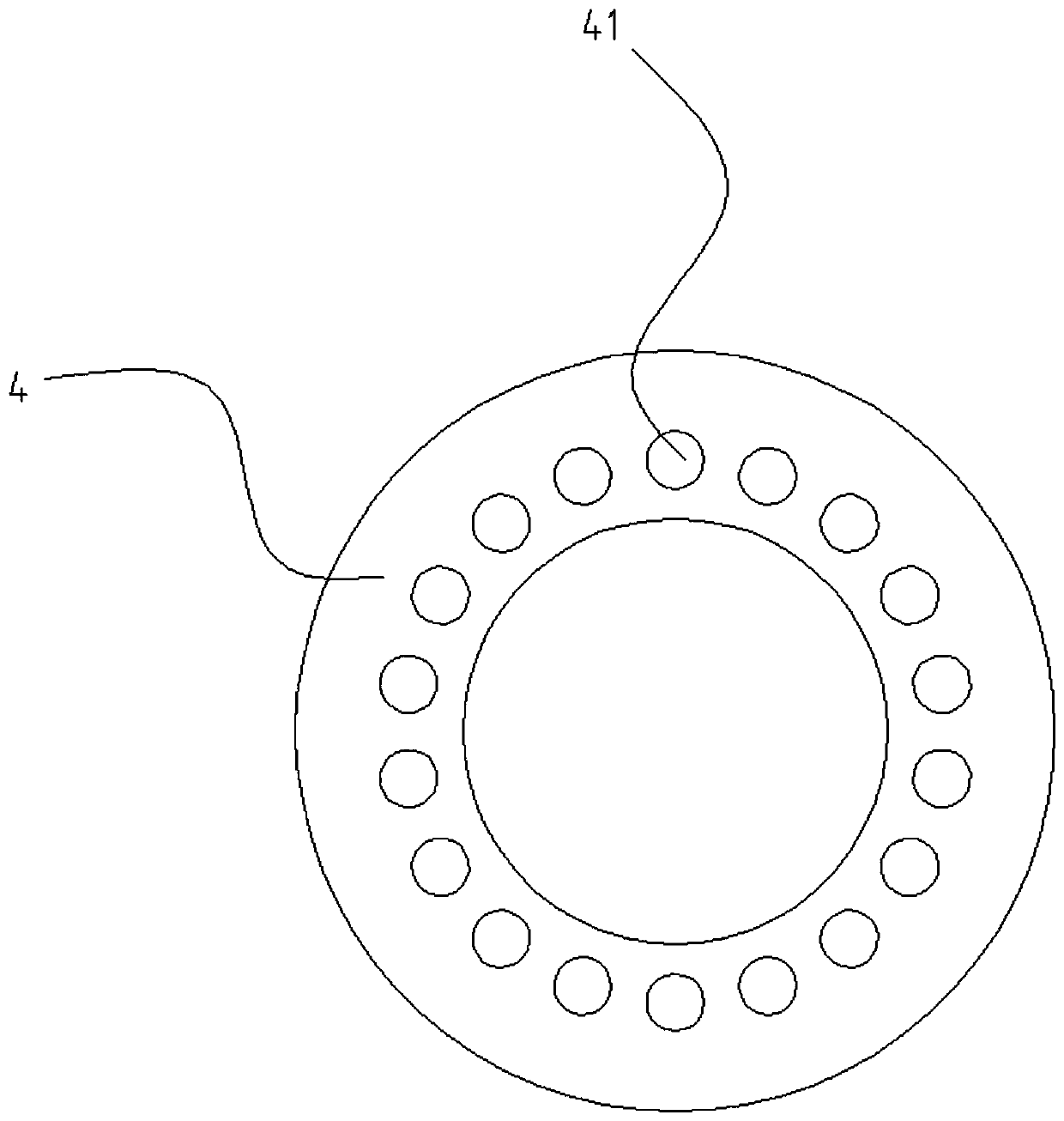
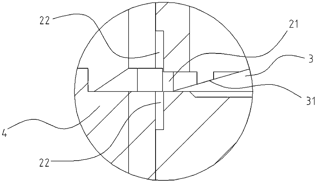
[0020] In order to make it easy to understand the technical means, creative features, goals and effects realized by the present invention, the following embodiments are combined with the appendix. figure 1 to the attached image 3 The technical solutions provided by the present invention are described in detail, but the following contents are not intended to limit the present invention.

[0021] figure 1 It is a structural diagram of an embodiment of a novel regenerative structure of the present invention; figure 2 It is a structural diagram of a hot-end gas guide ring from a viewing angle according to a preferred embodiment of the present invention; image 3 for figure 1 Enlarged view of section A in the middle. like figure 1 , figure 2 as well as image 3 As shown, the novel heat recovery structure provided in this embodiment includes: a piston 2 , a hot end vent hole 21 , an air guide groove 22 , an end plug 3 , a slope 31 , a hot end air guide ring 4 and an air gu...


PUM


Abstract

The invention provides a novel backheating structure and belongs to the technical field of Stirling motors. The novel backheating structure comprises a piston which is hollow and provided with a filler, a cold end ventilation hole is formed in the end face of one end, close to a cold end, of the piston, a hot end ventilation hole is formed in the side wall of one end, close to a hot end, of the piston, a hot end air guide ring with an air guide passage corresponding to the hot end ventilation hole sleeves the outer side of the piston, two ends of the air guide passage are respectively connected with the hot end ventilation hole and a Stirling motor hot end, an air guide groove is formed in the hot end ventilation hole, and an end plug with a bevel is arranged at the hot end ventilation hole in the piston. By arranging the filler in the hollow piston, a backheating function is realized, and heat leakage of a shell and the inside of the piston is reduced; by arranging the air guide groove, the hot end ventilation hole in the piston is constantly communicated with the hot end air guide ring, so that gas flow continuity is ensured; by arranging the piston with a cold end face being a plane and the shell, dead volume is eliminated, and performance is improved.

Description

technical field [0001] The invention relates to the technical field of Stirling motors, in particular to a novel heat recovery structure. Background technique [0002] The Stirling motor has a cold end and a hot end, and the gas needs to pass through the regenerative structure when flowing between the cold end and the hot end. Therefore, improving the performance of the regenerative structure of the Stirling motor is the focus of current research. [0003] At present, the regenerative structure of the Stirling motor on the market includes a hot end heat sink and a cold end heat sink, and a regenerator is arranged between the hot end heat sink and the cold end heat sink, and the hot end heat sink and the cold end heat sink The heat sink and the regenerator are annularly sleeved on the passage of the piston, so that the gas can continuously pass between the hot end heat sink, the regenerator and the cold end heat sink under the action of the piston to release energy. , this h...

Claims


Application Information

Patent Timeline
Patent Type & Authority Patents(China)
IPC IPC(8): F02G1/057
CPCF02G1/057
Inventor 程路
Owner CHINA STIRLING ENGINE MFG
Learn More