Two-grade pressure reducing disc and pressure reducing valve

A pressure reducing valve and body technology, applied in valve details, safety valves, balance valves, etc., can solve the problems of many parts, complex structure, and many parts used, and achieve fast speed, simple structure, and obvious pressure reduction effect. Effect

Active Publication Date: 2018-06-29
河南省中平防护设备制造有限公司
View PDF9 Cites 3 Cited by
  • Summary
  • Abstract
  • Description
  • Claims
  • Application Information

AI Technical Summary

Problems solved by technology

The bellows type pressure reducing valve is also called the direct acting pressure reducing valve. It is small in size and the most economical to use, but it is only used for the pressure reduction of high-pressure gas with medium and low flow; the piston type pressure reducing valve integrates the pilot valve and the main valve In one body, the exhaust pressure from the pilot valve acts on the piston, causing the piston to open the main va

Method used


Image

  • Two-grade pressure reducing disc and pressure reducing valve
  • Two-grade pressure reducing disc and pressure reducing valve
  • Two-grade pressure reducing disc and pressure reducing valve

Examples


Embodiment 1

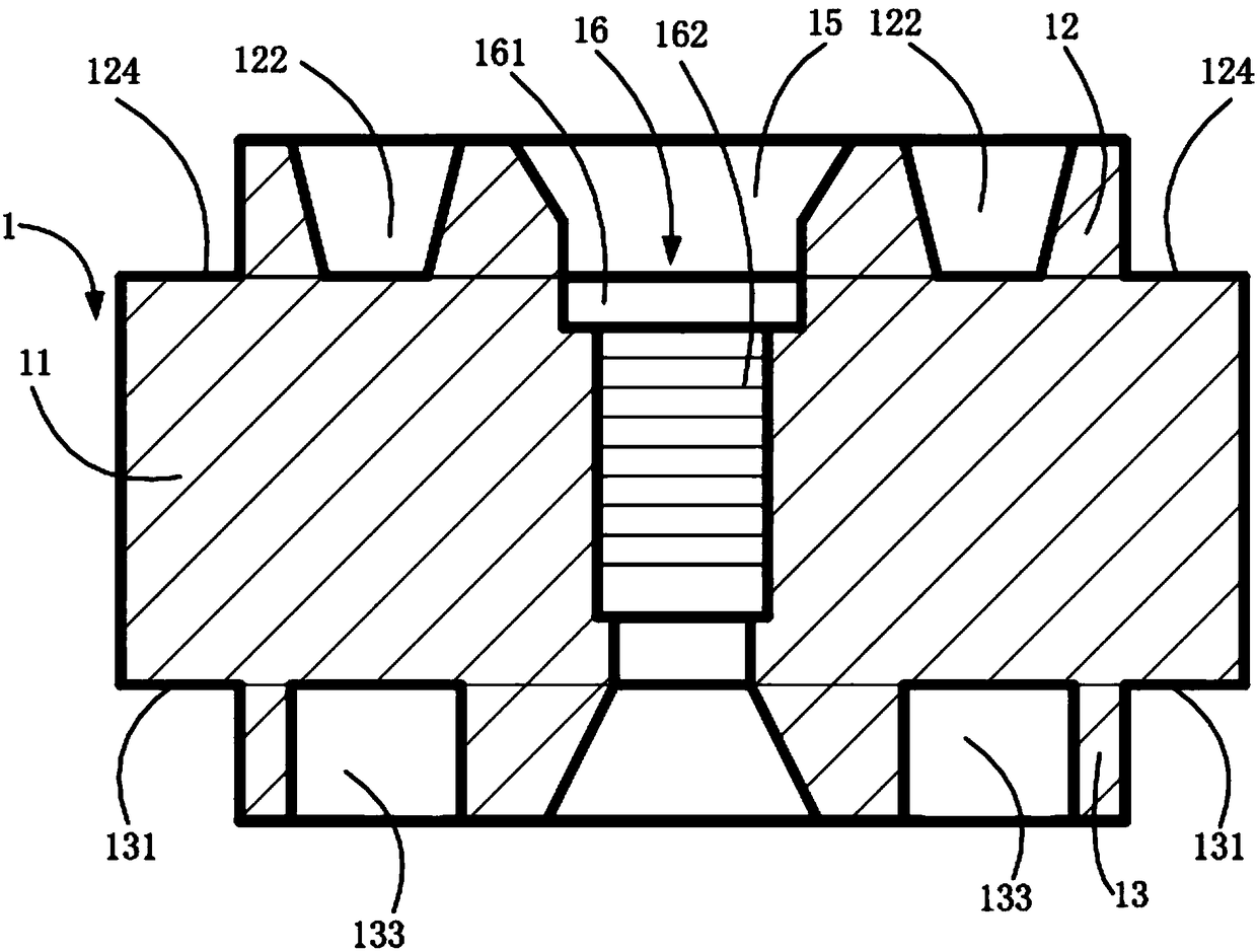
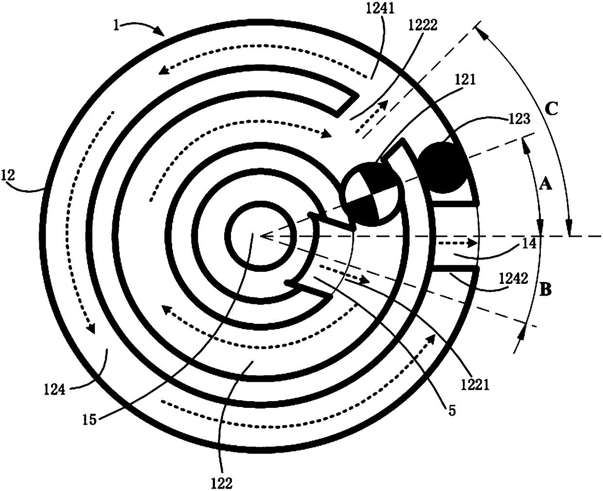
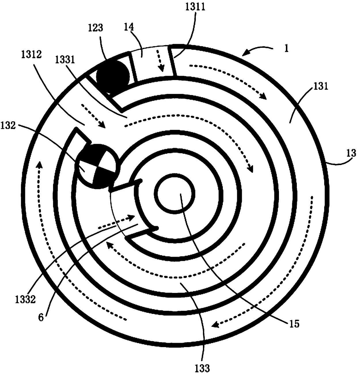
[0077] Please refer to figure 1 , is a cross-sectional view of the secondary decompression disk 1 in this embodiment. This embodiment provides a two-stage decompression disk 1 , which includes: a disk body 11 , a first rotating structure 12 , a second rotating structure 13 and an airflow groove 14 . Wherein, the disk body 11 is approximately cylindrical, which has an upper bottom surface, a peripheral side surface and a lower bottom surface; when the first rotating structure 12 moves the high-pressure gas along it, it forms a continuous rotating airflow direction with two different rotating diameters, which Centered on the center of the upper bottom surface of the disk body 11, the ring is set on the upper bottom surface of the disk body 11; the second rotating structure 13 also makes the high-pressure gas move along it, forming a continuous rotating airflow direction with two different rotating diameters, which is represented by The center of the bottom surface of the disk b...

Embodiment 2

[0082] Please refer to Figure 4 , is a cross-sectional view of the secondary pressure reducing valve in this embodiment. This embodiment provides a secondary pressure reducing valve, which includes: a shell barrel 2 , an air inlet cover 3 , an air outlet cover 4 and a secondary pressure reducing plate 1 . The air intake cover 3 is located on the top of the shell barrel 2, and an air intake 31 is provided on it, such as Figure 5 , the air intake cover 3 includes a first cover 32 and a second cover 33, the diameter of the first cover 32 is smaller than the diameter of the second cover 33, the first cover 32 is partially embedded in the second cover 33, the first The central axes of the cover body 32 and the second cover body 33 coincide, and the air inlet 31 extends from the first cover body 32 to the second cover body 33; the air outlet cover 4 is arranged at the bottom of the shell barrel 2, and an air outlet port is arranged on it 41 ; the secondary decompression plate 1 i...


PUM


Abstract

The invention discloses a two-grade pressure reducing disc and a pressure reducing valve. The pressure reducing disc comprises a disc body, a first rotating structure, a second rotating structure andan airflow groove, wherein the disc body is provided with an upper bottom surface, a peripheral side surface and a lower bottom surface; the first rotating structure is annularly arranged on the upperbottom surface of the disc body with the circle center of the upper bottom surface of the disc body as the center; the second rotating structure is annularly arranged on the lower bottom surface of the disc body with the circle center of the lower bottom surface of the disc body as the center; the airflow groove is arranged on the peripheral side surface of the disc body parallel to the center axis of the disc body; and two ends thereof respectively communicate with the first rotating structure and the second rotating structure. The pressure reducing valve comprises the pressure reducing disc. The two-grade pressure reducing disc and the pressure reducing valve are simple in structure and fewer in used part; the first rotating structure and the second rotating structure are arranged on the upper bottom surface and the lower bottom surface of the disc body; after high-pressure gas enters the pressure reducing valve, the airflow flowing direction is the rotary flowing direction, so thatthe potential energy is continuously reduced in the rotating process to achieve the purpose of pressure reduction, the pressure reducing effect is obvious, and the speed is higher; and when the pressure of the introduced high-pressure gas is higher, the pressure reducing ratio is higher.

Description

technical field [0001] The invention relates to the field of a gas decompression device, in particular to a two-stage decompression plate and a decompression valve. Background technique [0002] In the prior art, common pressure reducing valves mainly include bellows type pressure reducing valves, piston type pressure reducing valves and membrane type pressure reducing valves. The bellows type pressure reducing valve is also called the direct acting pressure reducing valve. It is small in size and the most economical to use, but it is only used for the pressure reduction of high-pressure gas with medium and low flow; the piston type pressure reducing valve integrates the pilot valve and the main valve In one body, the exhaust pressure from the pilot valve acts on the piston to make the piston open the main valve. The structure of the piston pressure reducing valve is complex and uses many parts, and if the main valve is too large to open directly, it needs external force Op...

Claims


Application Information

Patent Timeline
IPC IPC(8): F16K47/08F16K47/04F16K17/24
Inventor 黎转群
Owner 河南省中平防护设备制造有限公司
Why Eureka
Try Eureka