
Energy-saving hot air drying system and energy-saving hot air drying method

A technology of hot air drying and drying box, which is applied in the direction of drying gas arrangement, drying, drying machine, etc., to achieve the effect of easy removal, increase concentration, and reduce ineffective exhaust

Pending Publication Date: 2018-06-29
VERBOCA ENERGY SAVING TECH CO LTD
View PDF1 Cites 3 Cited by
  • Summary
  • Abstract
  • Description
  • Claims
  • Application Information

AI Technical Summary

Problems solved by technology

[0011] The present invention provides an energy-saving hot air drying system, which aims to solve the above-mentioned problems existing in the energy-saving hot air drying system in the prior art;
[0012] The present invention also provides an energy-saving hot air drying method, aiming to solve the above-mentioned problems existing in the energy-saving hot air drying method in the prior art

Method used


Image

  • Energy-saving hot air drying system and energy-saving hot air drying method
  • Energy-saving hot air drying system and energy-saving hot air drying method
  • Energy-saving hot air drying system and energy-saving hot air drying method

Examples


Embodiment 1

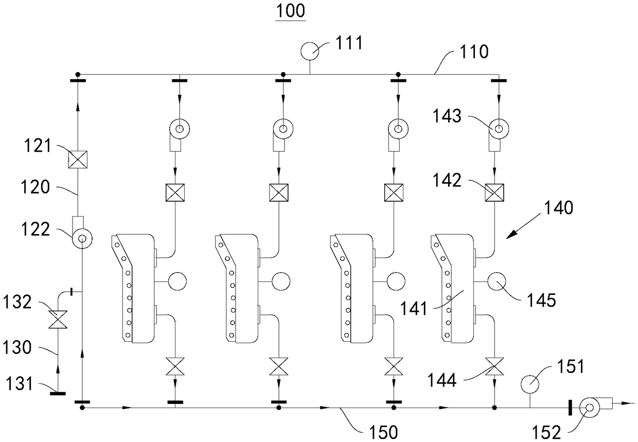
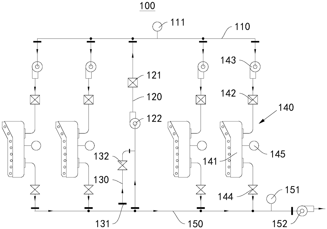
[0053] This embodiment provides an energy-saving hot air drying system 100, please refer to figure 1 , figure 2 , image 3 as well as Figure 4 , this energy-saving hot air drying system 100 includes:

[0054] Air supply duct 110;

[0055] Exhaust duct 150, exhaust duct 150 is connected with exhaust fan 152, exhaust fan 152 is used to discharge the gas in the exhaust duct 150 to the external environment;

[0056] A communication duct 120, one end of the communication duct 120 communicates with the air supply duct 110, and the other end communicates with the exhaust duct 150;

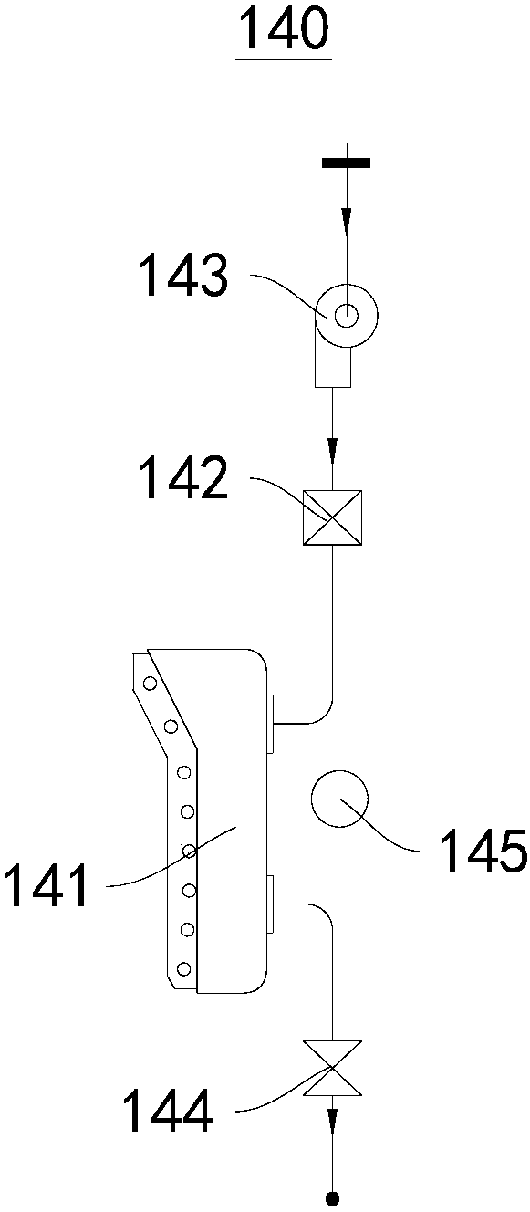
[0057] A plurality of drying units 140, one end of the plurality of drying units 140 is in communication with the air supply duct 110, and the other end is in communication with the exhaust duct 150;

[0058] The drying unit 140 includes: a drying box 141 and a blower fan 143, the blower fan 143 is connected to the drying box 141, and the blower fan 143 is used to discharge the gas in the air suppl...

Embodiment 2

[0095] This embodiment provides an energy-saving hot air drying method, which includes the following steps:

[0096] According to the feedback value of the first pressure sensor 111 , the frequency of the booster fan 122 is adjusted so that the inside of the air supply duct 110 is in a slightly negative pressure state.

[0097] Adjust the opening of exhaust valve 144 to the maximum, gradually increase the frequency of exhaust fan 152, until all are in the negative pressure state in the drying box 141, read the pressure value of the feedback of the second pressure sensor 151 at this time, adjust The frequency of the exhaust fan 152 makes the pressure in the exhaust duct 150 approach to this pressure value all the time.

[0098] Adjust the opening of the exhaust valve 144 one by one, so that the air pressure inside each drying box 141 is in a slightly negative pressure state.

[0099] Wherein, the slightly negative pressure state is that the relative pressure is between -100Pa~...


PUM


Abstract

The invention provides an energy-saving hot air drying system and an energy-saving hot air drying method, and belongs to the field of drying devices. The energy-saving hot air drying system comprisesan air supply pipeline, an exhaust pipeline, a communicating pipe and a plurality of drying units, wherein the exhaust pipeline is connected to an exhaust fan, one end of the communicating pipeline communicates with the air supply pipeline, and the other end of the communicating pipeline communicates with the exhaust pipeline; and one ends of the drying units communicate with the air supply pipeline, and the other ends of the drying units communicate with the exhaust pipeline. The energy-saving hot air drying method comprises the following steps that the frequency of a booster fan is adjustedto enable the air supply pipeline to be in a micro-negative pressure state; and the frequency of the exhaust fan and the opening degree of an exhaust valve are adjusted, so that the air pressure inside each drying box is in a micro-negative pressure state. The energy-saving hot air drying system and the energy-saving hot air drying method can be stopped when partial drying units do not need to work, so that the energy consumption can be reduced.

Description

technical field [0001] The invention relates to the field of drying devices, in particular to an energy-saving hot air drying system and an energy-saving hot air drying method. Background technique [0002] The drying system is the main energy consumption unit of printing, compounding, coating, spraying and painting production equipment, and it is also the main emission source of exhaust gas. The efficiency of the drying system is the core parameter of the production equipment performance evaluation index. [0003] Traditional drying system: The traditional drying system generally adopts a parallel drying system with multiple drying units. The air intake of each unit drying box is a unit independent air inlet directly sucking air from the production site, and the exhaust air of each unit drying box is connected in parallel to a The main exhaust duct is drawn and discharged by an exhaust fan. [0004] Side-by-side drying system with return air: There are also some improvemen...

Claims


Application Information

Patent Timeline
IPC IPC(8): F26B21/00F26B21/10
CPCF26B21/001F26B21/004F26B21/10
Inventor 简甦严翔邹霞张桂超
Owner VERBOCA ENERGY SAVING TECH CO LTD
Features
  • Generate Ideas
  • Intellectual Property
  • Life Sciences
  • Materials
  • Tech Scout
  • Unparalleled Data Quality
  • Higher Quality Content
  • 60% Fewer Hallucinations
Learn More