
Dehumidifier

A dehumidifier and pillar technology, applied in the field of machinery, can solve the problems of long time for taking out materials, lower production efficiency, and inconvenience in taking out materials by a dehumidifier, so as to achieve the advantages of convenient taking out, improving production efficiency and shortening taking out time. Effect

Inactive Publication Date: 2018-06-29
李少军
View PDF0 Cites 0 Cited by
  • Summary
  • Abstract
  • Description
  • Claims
  • Application Information

AI Technical Summary

Problems solved by technology

[0004] The purpose of the present invention is to provide a dehumidifier to solve the problem that the dehumidifier is inconvenient to take out the materials, and it takes a long time to take out the materials, which reduces the production efficiency.

Method used


Image

  • Dehumidifier
  • Dehumidifier
  • Dehumidifier

Examples


Embodiment Construction

[0029] The following will clearly and completely describe the technical solutions in the embodiments of the present invention with reference to the accompanying drawings in the embodiments of the present invention. Obviously, the described embodiments are only some, not all, embodiments of the present invention. Based on the embodiments of the present invention, all other embodiments obtained by persons of ordinary skill in the art without making creative efforts belong to the protection scope of the present invention.

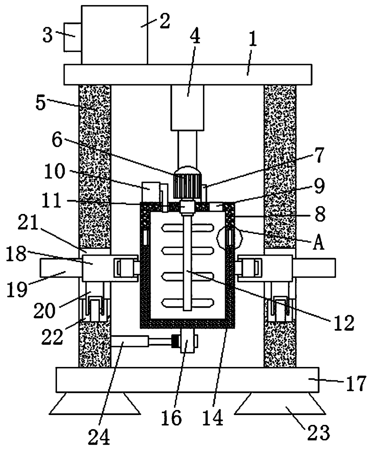
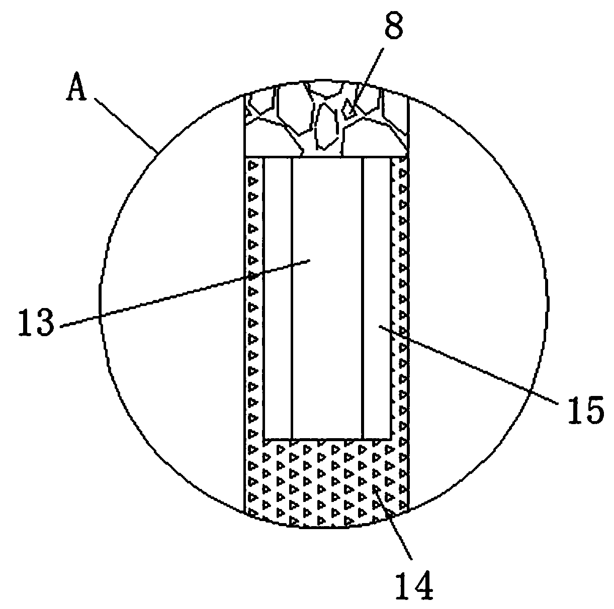
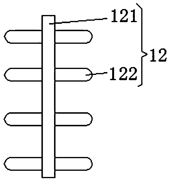
[0030] see Figure 1-6 , the present invention provides a technical solution: a dehumidifier, including an upper end plate 1, a chemical battery 2 is fixedly connected to the upper surface of the upper end plate 1, a control panel 3 is fixedly connected to the side of the chemical battery 2, and the lower side of the upper end plate 1 The surface is fixedly connected with a first automatic push rod 4 and two pillar plates 5, the first automatic push rod 4 is l...


PUM


Abstract

The invention discloses a dehumidifier which comprises an upper end plate. The upper surface of the upper end plate is fixedly connected with a chemical battery, the side face of the chemical batteryis fixedly connected with a control plate, the lower surface of the upper end plate is fixedly connected with a first automatic push rod and two abutment plates, the first automatic push rod is positioned between the two abutment plates, the bottom ends of the two abutment plates are fixedly connected with the upper surface of a lower end plate, and the bottom end of the first automatic push rod is fixedly connected with a motor. By the aid of the first automatic push rod, a second linear actuator, a first shell, a second shell, a turning table, a sliding mechanism, a square pit, a sliding rail, a fixing device, a first rocking bar and a second rocking bar, all materials positioned in the second shell are poured out once without a manual tool, so that the materials are more conveniently taken out, material take-out time is shortened, and material production efficiency is improved.

Description

technical field [0001] The invention relates to the technical field of machinery, in particular to a dehumidifier. Background technique [0002] The dehumidifier has several modes such as belt drying, drum drying, box drying, and tower drying; the heat source includes coal, electricity, gas, etc.; the drying process of materials has hot air flow type and radiation type, etc. , The hot air drum drying is that the hot air flow moves forward from the tail, fully contacts with the material, and makes full use of the heat transfer through heat conduction, convection and radiation; the heat energy is directly transferred to the material, so that the moisture of the material is continuously evaporated in the cylinder, and the material is fed into the cylinder. The air-introducing device at the outlet extracts a large amount of water and wet air to prevent secondary pollution caused by dust discharge; the material movement is promoted through internal spiral stirring, sweeping and l...

Claims


Application Information

Patent Timeline
IPC IPC(8): F26B25/00F24F3/14F24F13/00
CPCF26B25/00F24F3/14F24F13/00F24F2003/144
Inventor 李少军
Owner 李少军
Features
  • Generate Ideas
  • Intellectual Property
  • Life Sciences
  • Materials
  • Tech Scout
  • Unparalleled Data Quality
  • Higher Quality Content
  • 60% Fewer Hallucinations
Learn More