
A water chamber arrangement method and arrangement structure of a water-cooled condenser

A condenser and water condensation technology, applied in steam/steam condensers, heat exchanger shells, lighting and heating equipment, etc., can solve the problems affecting the stability and reliability of water-cooled condensers and the manufacturing cost of water-cooled condensers increase, weak compressive capacity, etc., to achieve the effect of simple structure, compact structure volume and high compressive strength

Active Publication Date: 2019-10-18
DONGFANG TURBINE CO LTD
View PDF7 Cites 0 Cited by
  • Summary
  • Abstract
  • Description
  • Claims
  • Application Information

AI Technical Summary

Problems solved by technology

However, in the actual working process of the water-cooled condenser, due to the high pressure of the water flowing into the water-side of the water-cooled condenser, especially the return water of the heating network is the most obvious, which will make the return water with a large structural volume The pressure resistance of the chamber to the high-pressure water flow is weak, which directly affects the stability and reliability of the operation of the water-cooled condenser. This puts forward high technical requirements for the design of the pressure resistance of the back-bent water chamber. The conventional solution is Significantly increase the compressive structural strength of the curved water chamber, or even the entire condenser shell, to effectively match the working pressure of the high-pressure water flow, but this solution will inevitably increase the manufacturing cost of the water-cooled condenser and affect the economy. sex

Method used


Image

  • A water chamber arrangement method and arrangement structure of a water-cooled condenser
  • A water chamber arrangement method and arrangement structure of a water-cooled condenser
  • A water chamber arrangement method and arrangement structure of a water-cooled condenser

Examples


Embodiment 1

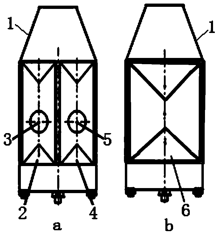
[0024] The present invention is a method for arranging water chambers of a water-cooling condenser with a double-flow structure in the left and right directions. A fluid return bending area between the water chamber and the outlet water chamber process. The function of the fluid return bending area is to turn the water flow from the inlet water chamber through the heat exchange chamber in the left and right directions and guide it to enter the outlet water chamber through the heat exchange chamber. . In the present invention, the fluid return bending area at the rear side of the water-cooling condenser is divided into two space-independent return areas along the direction of the return bending of the fluid, that is, the left and right directions, in a manner of diverting and controlling the return bending fluid (ie, water flow). For water bend chambers, it is best to follow the principle of equal division for the division of multiple bend water chambers in the same fluid retur...

Embodiment 2

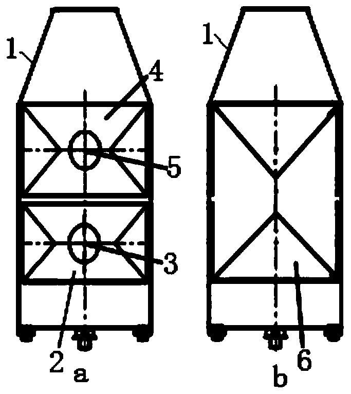
[0027] The present invention is a method for arranging water chambers of a water-cooling condenser with a double-flow structure in the up-and-down direction. A fluid return bending area between the water chamber and the outlet water chamber process, the function of the fluid return bending area is to turn the water flow from the inlet water chamber through the heat exchange chamber in the up and down direction and guide it to enter the outlet water chamber through the heat exchange chamber . In the present invention, the fluid return bending area at the rear side of the water-cooling condenser is divided into two space-independent return areas along the direction of the return bending of the fluid, i.e., the up and down direction, in a way of diverting and controlling the return bending fluid (ie, water flow). For water bend chambers, it is best to follow the principle of equal division for the division of multiple bend water chambers in the same fluid return bend area, so as ...

Embodiment 3

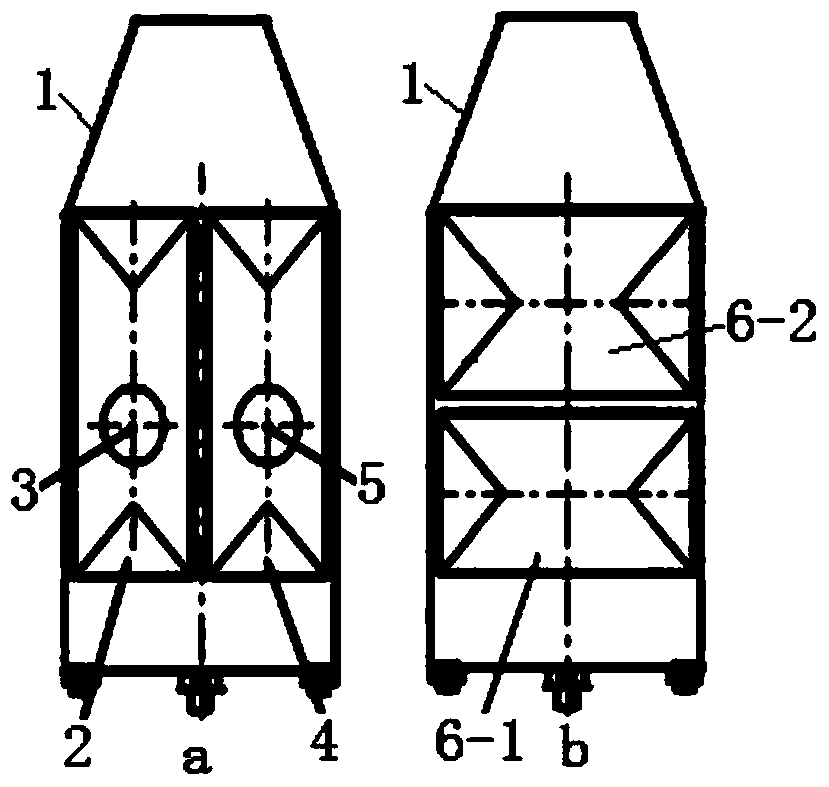
[0030] The present invention is a method for arranging water chambers of a water-cooled condenser with a multi-flow structure in the left and right directions. The front side of the water-cooled condenser has an inlet water chamber arranged in a left, middle and right direction, a fluid return bending area and an outlet water chamber. , a fluid return bend area on the front side is between the processes of the water inlet chamber and the water outlet chamber arranged left and right, and the rear side has two fluid return bends between the processes of the water inlet chamber and the outlet water chamber area, the fluid return bending areas on the rear side and front side of the condenser should be arranged correspondingly according to the flow sequence set between the inlet water chamber and the water outlet water chamber process; the function of each fluid return bending area is to The water flow from the water chamber through the heat exchange chamber is guided by turning aro...


PUM


Abstract

The invention discloses a water chamber arrangement method and arrangement structure of a water-cooled condenser. The arrangement method is to divide and set the same fluid return bend area on the condenser along the return bend direction of the fluid into a plurality of return bend water chambers that are independent of each other in space by controlling the return flow of the return bend fluid, so that Fluids in the same fluid bending area flow separately in a multi-channel manner. The present invention will not affect the heat exchange effect of the condenser, but can make the structure volume of each curved water chamber in the same fluid curved area miniaturized and compacted, thereby reliably lifting and strengthening each curved water chamber The compressive capacity of the utility model can effectively match the working pressure of the high-pressure water flow, especially the return water of the heating network. The invention has the characteristics of simple structure, convenient manufacture, low manufacturing cost, high compressive strength, stable operation, etc., and has remarkable economic benefits.

Description

technical field [0001] The invention relates to a water cooling condenser of a steam turbine unit, in particular to a high back pressure condenser of a steam turbine unit of a thermal power plant, in particular to an arrangement method and arrangement structure of a water chamber of a water cooling condenser. Background technique [0002] The condenser is a heat exchanger that condenses the exhaust steam of the steam turbine into water. It is divided into water-cooled condensers and air-cooled condensers according to the different condensing media. Among them, the water-cooled condenser is widely used in thermal power plants. By passing the water side of the water-cooled condenser into the circulating water of the heating network, it can achieve the purpose of reusing the waste heat of exhausted steam after power generation and improving economic benefits. High back pressure A condenser is a common one. [0003] The main structure and working principle of the water-cooled c...

Claims


Application Information

Patent Timeline
Patent Type & Authority Patents(China)
IPC IPC(8): F28B1/02F28F9/02
Inventor 郑雯颜强高晓亮姬艳云周进游克华米沛
Owner DONGFANG TURBINE CO LTD
Learn More