
Optical heating window of camera

A window and optical technology, applied in the field of camera optical heating window, can solve problems such as easily affecting camera imaging, achieve good heating effect, strong environmental adaptability, and improve the effect of defogging

Pending Publication Date: 2018-06-29
XI'AN INST OF OPTICS & FINE MECHANICS - CHINESE ACAD OF SCI
View PDF13 Cites 3 Cited by
  • Summary
  • Abstract
  • Description
  • Claims
  • Application Information

AI Technical Summary

Problems solved by technology

[0012] The object of the present invention is to provide a camera optical heating window, which solves the technical problems of the existing camera optical window defrosting, poor fog effect and easily affecting camera imaging

Method used


Image

  • Optical heating window of camera
  • Optical heating window of camera
  • Optical heating window of camera

Examples


Embodiment Construction

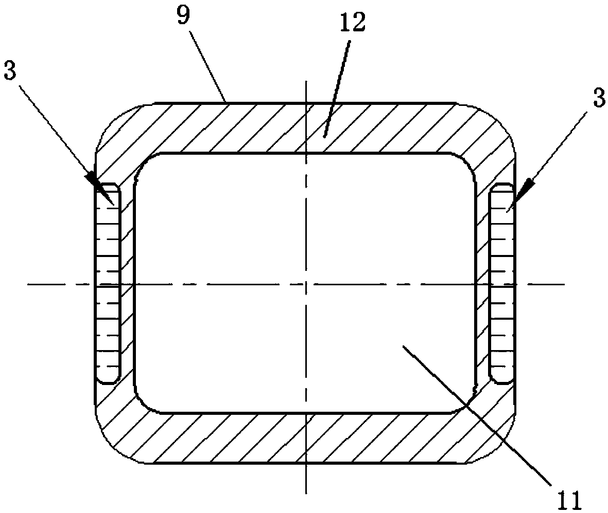
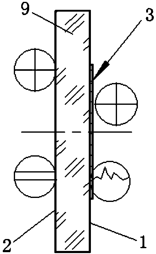
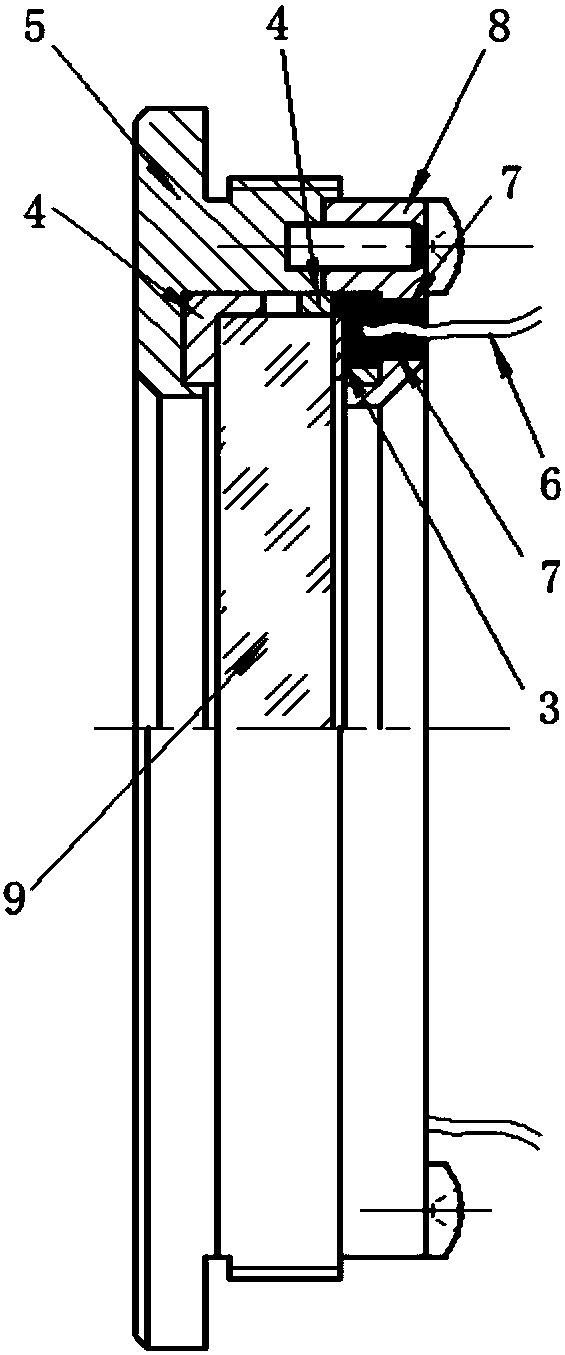
[0033] The optical heating window is located in the optical path at the front end of the optical system. The window should first meet the requirements of the optical system for the window material in terms of bubble degree, uniformity, fluorescence characteristics, refractive index consistency, and stress birefringence; secondly, the optical heating window should meet the requirements of the optical system. The surface accuracy (aperture, partial aperture, PV, RMS) and the parallelism error of the two surfaces of the window (the actual value can be selected according to the optical system). In addition, the optical heating window should not only meet the functions of heating defrosting and defogging, but also have a high transmittance and prevent ghost images under strong light. For this reason, the present invention innovatively proposes a ring-shaped conductive film design scheme, in which an anti-reflection film is coated inside the optical aperture of the optical system, an...


PUM


Abstract

The invention belongs to the technical field of optical imaging and particularly relates to an optical heating window of a camera. The optical heating window structurally comprises a window body, wherein the window body comprises a first surface and a second surface; the first surface comprises a light transmitting zone located in the center and a heating zone surrounding the light transmitting zone, and a conductive film is arranged on the heating zone and connected with a heating circuit. The technical problems that existing optical windows of cameras have poor defrosting and demisting effects and affect camera imaging easily are solved. The annular conductive film is arranged to heat the optical window of the camera, uniform and quick heating can be realized, the heating effect is good,the window transmittance is high, no effects are caused to optical system imaging, and the heating wire shielding problem is avoided. The window cannot produce stray light such as ghost images understrong light and is particularly applicable to cameras or video cameras working in humid and cold environments.

Description

technical field [0001] The invention belongs to the technical field of optical imaging, and in particular relates to an optical heating window of a camera. Background technique [0002] Heated windows are commonly used as windshields or rear lights in vehicles to enable defogging or defrosting of the windows during cold or wet weather conditions. The optical window for the camera is located at the forefront of the optical path, and is generally a round or square flat plate. In order to prevent the window from fogging and frosting in cold or humid weather and affecting the camera observation, in addition to the defogging and defrosting functions of the window, it is necessary to consider , but also to meet the optical requirements of optical system imaging for window surface accuracy, firmness, and stray light. [0003] Existing camera optical windows usually use active heating methods to defog and defrost. Window heating should not only consider the heating performance, bu...

Claims


Application Information

Patent Timeline
Patent Type & Authority Applications(China)
IPC IPC(8): G03B17/55
CPCG03B17/55
Inventor 闫阿奇张志武力梅超曹剑中杨洪涛王浩
Owner XI'AN INST OF OPTICS & FINE MECHANICS - CHINESE ACAD OF SCI
Learn More