An engine ignition switch and its automatic manufacturing system

An automatic manufacturing system, ignition switch technology, applied in the direction of electrical switches, contact electrical connections, electrical components, etc., can solve the problems of low production efficiency, prone to waste products, etc., to reduce labor costs, avoid leakage, and simplify complexity. Effect

Active Publication Date: 2019-07-23
宁波英格塑料制品有限公司
View PDF2 Cites 0 Cited by
  • Summary
  • Abstract
  • Description
  • Claims
  • Application Information

AI Technical Summary

Problems solved by technology

[0006] The purpose of the present invention is to solve the problems of low production efficiency and easy waste products in the existing manufacturing process of engine ignition switch, and provide an engine ignition switch and its automatic manufacturing system, which can significantly improve production efficiency and reduce labor costs. cost, and at the same time help to improve the pass rate of products

Method used


Image

  • An engine ignition switch and its automatic manufacturing system
  • An engine ignition switch and its automatic manufacturing system
  • An engine ignition switch and its automatic manufacturing system

Examples


Embodiment 1

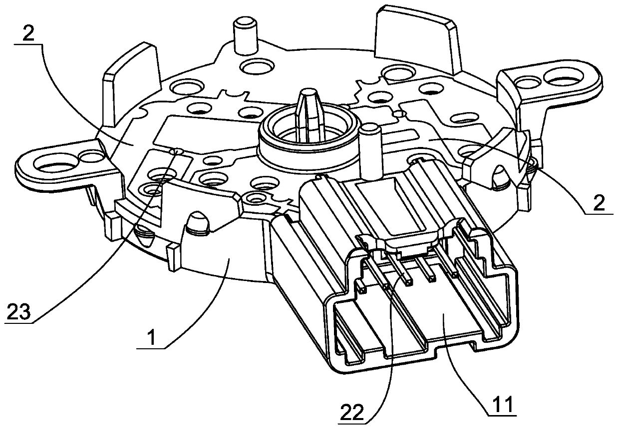
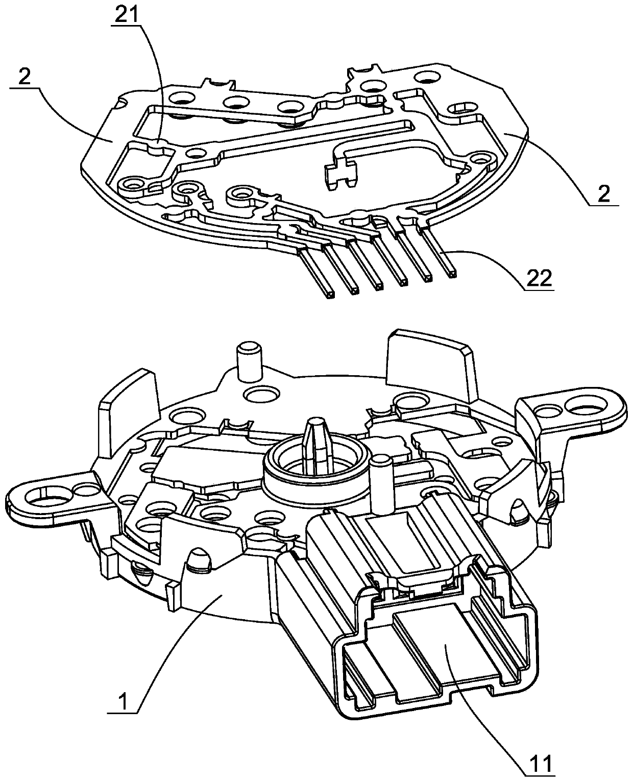
[0026] Embodiment 1: as figure 1 , figure 2 , image 3 , Figure 4As shown, an engine ignition switch includes an injection-molded base 1, six copper return bars 2 embedded in the base, and eight connecting parts 21 integrally arranged between adjacent return bars. , a number of resistors (not shown in the figure), the base has a connection jack 11, each return bar includes a connection terminal 22, and 6 connection terminals are equidistantly located in the connection socket of the base. Welding jacks 23 are arranged on the connecting portion, and the pins of the resistance are inserted in the welding jacks of the corresponding connecting portion and welded together with the connecting portion. The connected return bars are connected radially outside the connecting portion.

[0027] In this way, all the reflow bars are connected to form an integral structure through the connecting portion, and thus can be integrally formed by means of a stamping process or a casting proc...

Embodiment 2

[0030] Embodiment 2: An automatic manufacturing system of an engine ignition switch, which is suitable for automatic production of the engine ignition switch in Embodiment 1. like Figure 5 As shown, it specifically includes a base forming mold (not shown in the figure), an assembly platform 3, and the base forming mold is installed on a corresponding injection molding machine so as to injection mold the base of the engine ignition switch. In addition, a circular punching turntable 4, a punching upper die 5 that can move up and down, a vibrating plate (not shown in the figure) that can automatically sort and transport materials, and a linear vibrating feeder 6 are set on the assembly platform. Two punching lower dies 41 that can be matched with the punching upper die are arranged on the hole turntable, and the two punching lower dies are evenly distributed in the circumferential direction of the punching turntable, wherein the punching lower die located below the punching uppe...


PUM


Abstract

The invention discloses an engine ignition switch and an automatic manufacturing system of the engine ignition switch. The ignition switch comprises a base, a plurality of backflow strips with terminals, and a resistor, wherein a connecting part is arranged between the adjacent backflow strips, a welding jack is formed in the connecting part, a pin of the resistor is inserted and welded in the corresponding welding jack, the manufacturing system comprises a base forming mold and an assembling platform, a punching turntable and a punching upper die are arranged on the assembling platform, two punching lower dies are arranged on the punching turntable, one punching lower die is located in the punching position, the other punching lower die is located in the charging position, well-formed semi-finished products are put in a vibrating disc, are ordered and fall into a linear vibrating feeder, a first manipulator grabs the semi-finished product to the punching lower die in the charging position, the punching turntable rotates by 180 degrees, then the punching lower die loaded with the semi-finished product is transferred to the punching position, and the welding jack is punched in the connecting part of the semi-finished product. The engine ignition switch and the automatic manufacturing system of the engine ignition switch improve the production efficiency, reduce the labor cost, and are favorable for improving the product quality at the same time.

Description

technical field [0001] The invention relates to the technical field of engine ignition switch manufacturing, in particular to an engine ignition switch and an automatic manufacturing system that is beneficial to realize automatic production. Background technique [0002] The engine ignition switch is an essential component of the car. There are many structural forms of the existing engine ignition switch. One of the common engine ignition switches includes a plastic base, and several return bars and Resistor, the base has a connecting jack and several welding jacks for inserting the pins of the resistor, the reflow bar is embedded in the base, one end of the reflow bar is provided with a terminal in the connecting jack, the reflow bar The other end of the resistor is provided with at least one soldering point close to the soldering socket, and the pins of the resistor are plugged into the soldering socket and welded to the soldering point of the corresponding reflow bar. Af...

Claims


Application Information

Patent Timeline
Patent Type & Authority Patents(China)
IPC IPC(8): H01H9/02H01H1/58H01H11/00
CPCH01H1/58H01H9/02H01H9/0271H01H11/00
Inventor 应乐蒋挺
Owner 宁波英格塑料制品有限公司
Why Eureka
Try Eureka