
Electroluminescent display panel and packaging method thereof as well as display device

An electroluminescence display and panel technology, which is applied in the direction of circuits, electrical components, and electric solid devices, can solve the problems of water blocking and oxygen blocking performance reduction, and achieve the effect of improving water blocking and oxygen blocking performance

Inactive Publication Date: 2018-06-29
BOE TECH GRP CO LTD +1
View PDF4 Cites 11 Cited by
  • Summary
  • Abstract
  • Description
  • Claims
  • Application Information

AI Technical Summary

Problems solved by technology

[0005] Embodiments of the present invention provide an electroluminescent display panel, its packaging method, and a display device, which are used to solve the problem in the prior art that the performance of water and oxygen barriers is reduced due to cracks at the edge of the packaging film.

Method used


Image

  • Electroluminescent display panel and packaging method thereof as well as display device
  • Electroluminescent display panel and packaging method thereof as well as display device
  • Electroluminescent display panel and packaging method thereof as well as display device

Examples


Embodiment 1

[0055] In specific implementation, in the above-mentioned packaging method provided by the embodiment of the present invention, the packaging film covering the display area, the barrier wall and the peripheral area of ​​the barrier wall is formed, which may specifically include:

[0056] An encapsulation film with a hollow structure covering the display area, the retaining wall and the peripheral area of ​​the retaining wall is formed by using an evaporation process under the shield of the mask plate. In this way, excessive patterning process can be avoided, and the process preparation process can be reduced.

[0057] Specifically, the following steps may be included:

[0058] (1) Forming a first inorganic encapsulation layer with a hollow structure covering the display area, the retaining wall, and the peripheral area of ​​the retaining wall by using an evaporation process under the shielding of the first mask. Wherein, the shielding area of ​​the first mask plate correspond...

Embodiment 2

[0062] In specific implementation, in the above-mentioned packaging method provided by the embodiment of the present invention, the packaging film covering the display area, the barrier wall and the peripheral area of ​​the barrier wall is formed, which may specifically include:

[0063] A patterning process is used to form an encapsulation film covering the display area, the retaining wall and the peripheral area of ​​the retaining wall;

[0064] A photolithography process is used to form a hollow structure in a part of the peripheral area of ​​the barrier wall by the encapsulation film.

[0065] Specifically, the following steps may be included:

[0066] (1) A first inorganic encapsulation layer is formed on the array substrate on which the barrier walls are formed by using one patterning process. Wherein, the formed first inorganic encapsulation layer covers the display area, the barrier wall and the peripheral area of ​​the barrier wall.

[0067] (2) An organic encapsula...


PUM


Abstract

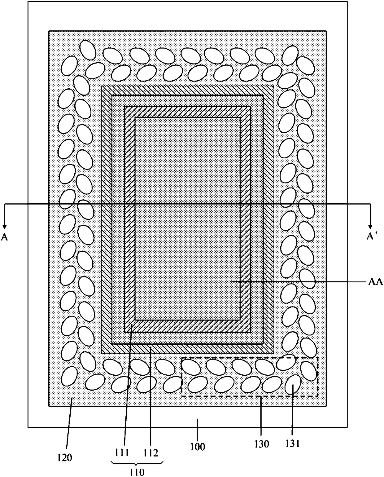
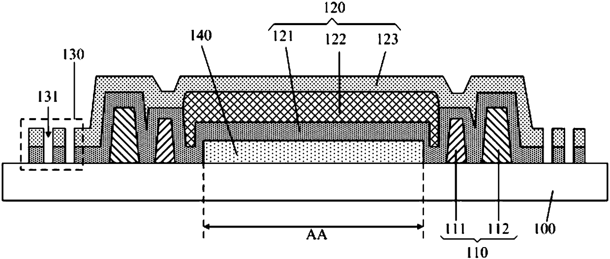
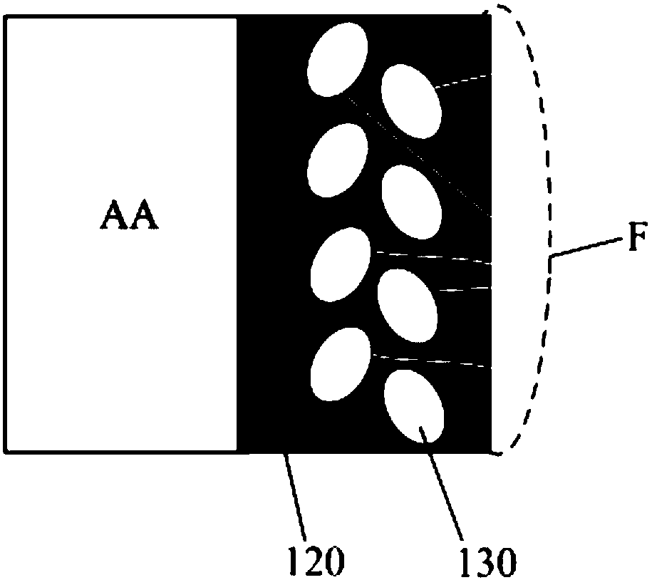
The invention discloses an electroluminescent display panel and a packaging method thereof as well as a display device. A partial area, at the periphery of a retaining wall, of a packaging thin film is arranged into a hollow-out structure, i.e., the edge of the packaging film is subjected to patterned design, and cracks on the edge of the packaging film caused by the subsequent technological preparation or transportation process of the electroluminescent display panel can be blocked off, so that water blocking and oxygen resisting properties are improved.

Description

technical field [0001] The invention relates to the field of display technology, in particular to an electroluminescence display panel, a packaging method thereof and a display device. Background technique [0002] Compared with liquid crystal display (Liquid Crystal Display, LCD), organic light-emitting diode (Organic Light-Emitting Diode, OLED) display has light and thin, wide viewing angle, active light emission, fast response speed, low energy consumption, low driving voltage, high luminous efficiency, As well as the advantages of flexible display, it has received extensive attention. [0003] A general OLED display panel includes an array substrate, an OLED device disposed on the array substrate, and an encapsulation film; wherein, the OLED device may include: an anode, a cathode, and an organic light-emitting layer between them. Due to the extremely poor resistance of the organic light-emitting layer and electrodes to water vapor and oxygen, it is easy to react with t...

Claims


Application Information

Patent Timeline
Patent Type & Authority Applications(China)
IPC IPC(8): H01L51/52H01L27/32
CPCH10K59/12H10K50/844
Inventor 刘阳升王伟金楻彭川
Owner BOE TECH GRP CO LTD
Learn More