Piezoresistive sensors, pressure detection devices, electronic equipment

An electronic equipment, piezoresistive technology, applied in the fields of piezoresistive sensors, pressure detection devices, and electronic equipment, can solve the problem of high internal space requirements, achieve low internal space requirements, suppress temperature drift, and avoid the effect of structural design

Active Publication Date: 2020-01-03
SHENZHEN GOODIX TECH CO LTD
View PDF8 Cites 0 Cited by
  • Summary
  • Abstract
  • Description
  • Claims
  • Application Information

AI Technical Summary

Problems solved by technology

However, this design method has relatively high requirements on the internal space of the entire electronic device, and it is also very important for the coordination, tolerance control, assembly, and factory test of the first pole plate 41, the second pole plate 42, the cover plate 2, and the carrier plate 5. have higher requirements

Method used


Image

  • Piezoresistive sensors, pressure detection devices, electronic equipment
  • Piezoresistive sensors, pressure detection devices, electronic equipment
  • Piezoresistive sensors, pressure detection devices, electronic equipment

Examples


Embodiment Construction

[0059] In order to make the object, technical solution and advantages of the present invention clearer, various embodiments of the present invention will be described in detail below in conjunction with the accompanying drawings. However, those of ordinary skill in the art can understand that, in each implementation manner of the present invention, many technical details are provided for readers to better understand the present application. However, even without these technical details and various changes and modifications based on the following implementation modes, the technical solution claimed in this application can also be realized.

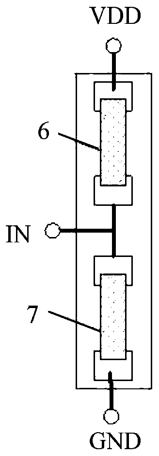
[0060] A first embodiment of the invention relates to a piezoresistive sensor. like figure 2 As shown, the piezoresistive sensor includes a substrate and a half-bridge piezoresistive sensing unit. When the half-bridge piezoresistive sensing unit realizes the pressure detection function, it can suppress the temperature drift and increase ...


PUM


Abstract

A piezoresistive sensor, a pressure measurement device and an electronic device, relating to the technical field of electronic devices. The piezoresistive sensor comprises substrates (12), and half-bridge type piezoresistive sensing units; each of the half-bridge type piezoresistive sensing unit comprises two bridge arms (6, 7), the two bridge arms being connected in series; signal acquisition ends (IN) are led out from the connecting ends of the two bridge arms (6, 7); excitation signal applying ends are led out from the opening ends of the two bridge arms (6, 7) respectively; each of the bridge arms (6, 7) comprises at least one resistor unit (101, 102, 103, 104); the resistor units (101, 102, 103, 104) are disposed on the substrates (12); and each of the bridge arms (6, 7) comprises the same number of the resistor units (101, 102, 103, 104). The piezoresistive sensor can inhibit temperature drift and increase semaphore while implementing the pressure measurement function; and the piezoresistive sensor has low requirement for the internal space of the entire electronic device and can be easily popularized.

Description

technical field [0001] The invention relates to the field of electronic technical equipment, in particular to a piezoresistive sensor, a pressure detection device and electronic equipment. Background technique [0002] In the prior art, the pressure detection scheme of the electronic equipment is mainly based on the capacitance sensor for detection. like figure 1 As shown, the principle of this solution is to use the finger 1 to press the cover plate 2 . The pressure exerted by the finger 1 is transmitted to the first plate 41 of the capacitive sensor 4 through the cover plate 2 . The first pole plate 41 deforms under force, so that the distance between the first pole plate 41 and the second pole plate 42 changes. Therefore, the capacitance value of the capacitive sensor 4 changes, so the detection of pressure can be realized according to the above principle. [0003] However, in the process of implementing the present invention, the inventor found the following technica...

Claims


Application Information

Patent Timeline
Patent Type & Authority Patents(China)
IPC IPC(8): G06F3/041G06F3/045G01L1/18
CPCG01L1/18G06F3/0414G06F3/045G06F3/041
Inventor 文达飞冉锐陈淡生
Owner SHENZHEN GOODIX TECH CO LTD
Why Eureka
Try Eureka