Methods and systems for scatter correction in positron emission tomography

An imaging system and tomographic imaging technology are applied in the fields of radiodiagnostic instruments, diagnosis, and applications, which can solve problems such as unknown radioactive activity and difficult scattering

Active Publication Date: 2018-07-03
GENERAL ELECTRIC CO
View PDF7 Cites 3 Cited by
  • Summary
  • Abstract
  • Description
  • Claims
  • Application Information

AI Technical Summary

Problems solved by technology

However, scattering events may originate outside the axial FOV of the scanner
Estimating out-of-field (OOF) scatter can be difficult without knowing the activity outside the axial FOV
In some types of imaging, such as prospective scans and reconstructions, the radioactivity outside the axial FOV may be unknown

Method used


Image

  • Methods and systems for scatter correction in positron emission tomography
  • Methods and systems for scatter correction in positron emission tomography
  • Methods and systems for scatter correction in positron emission tomography

Examples


Embodiment Construction

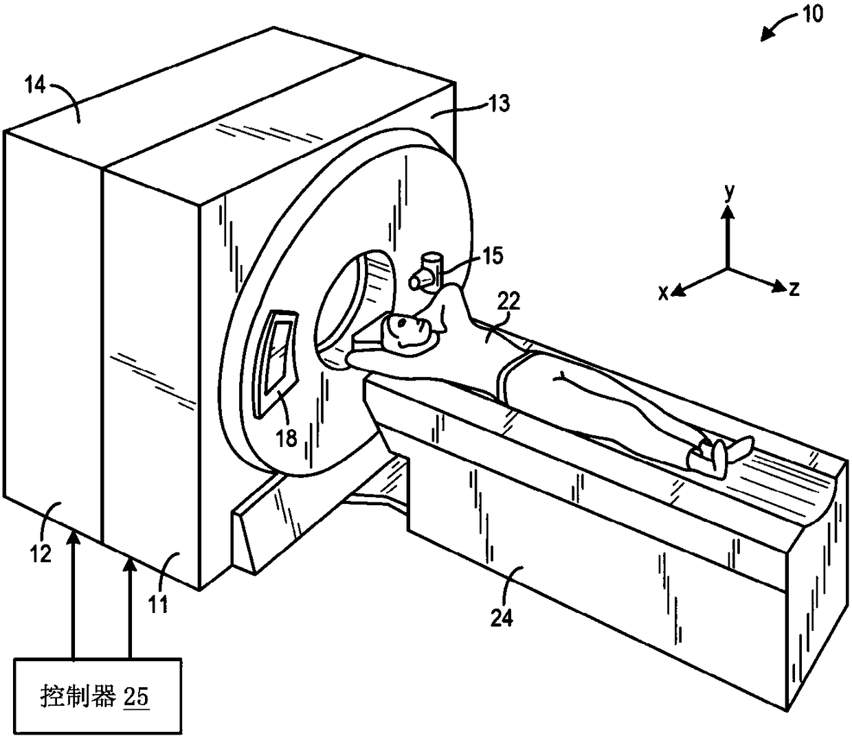
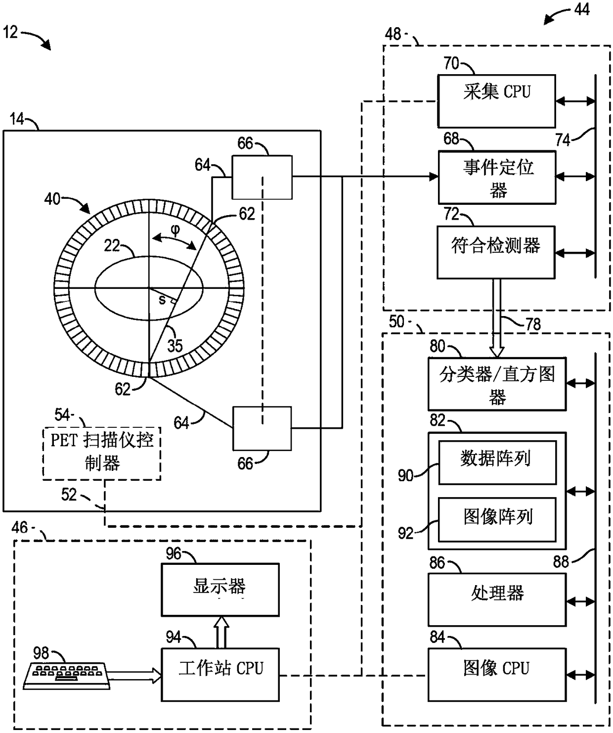
[0012] The following description relates to various embodiments of a medical imaging system. In particular, methods and systems are provided for compensating for out-of-field (OOF) scatter events using computed tomography (CT) image segmentation. figure 1 An example of an imaging system that can be used to acquire images processed according to the present technique is provided in . In this specification, the imaging system may be a multimodality system. In one embodiment, the multimodal imaging system may be a computed tomography / positron emission tomography (CT / PET) imaging system, wherein the first modality is a CT imaging system and the second modality is a PET imaging system (e.g. ,Such as figure 1 and figure 2 shown).

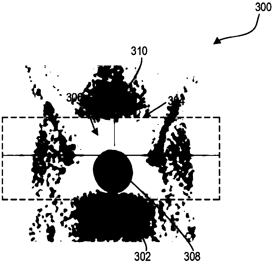
[0013] When scanning an object with a PET imaging system, scatter events that occur outside the scanner's axial field of view (FOV) can contaminate the signal reaching the imaging system's detector assembly. Such out-of-field (OOF) scattering events ...


PUM


Abstract

Methods and systems are provided for medical imaging systems. In one embodiment, a method comprises estimating an external scatter contamination in emission data based on an estimated emission activity originating from anatomies outside a field-of-view (FOV) of a scanner, the anatomies identified based on an image segmentation analysis performed on an image generated in the imaging system, the image generated prior to acquiring the emission data. In this way, a scatter correction applied to the emission data may include both scatter originating within the FOV and outside the FOV, and hence maybe more accurate.

Description

technical field [0001] Embodiments of the subject matter disclosed herein relate to non-invasive diagnostic imaging, and more particularly to image reconstruction using positron emission tomography (PET). Background technique [0002] PET generates images representative of the distribution of positron-emitting nuclides in the patient's body. When a positron interacts with an electron through annihilation, the entire mass of the positron-electron pair is converted into two 511-keV photons (also known as a 511-keV event). Photons are emitted in opposite directions along the line of response (LOR). Annihilation photons are detected by detectors placed on either side of the LOR in a configuration such as a detector ring. Detectors convert incident photons into useful electrical signals that can be used for image formation. The image thus generated based on the acquired image data includes annihilation photon detection information. [0003] The emitted photons are mostly scat...

Claims


Application Information

Patent Timeline
Patent Type & Authority Applications(China)
IPC IPC(8): G06T11/00G06T7/11G06T7/12G06T7/136
CPCG06T7/136G06T7/12G06T7/11G06T11/005G06T2207/10104G06T2211/416A61B6/488A61B6/5235A61B6/545A61B6/5282A61B6/032A61B6/037A61B6/5205A61B6/4417
Inventor 金肖钱华付赓
Owner GENERAL ELECTRIC CO
Why Eureka
Try Eureka