Device and method for lively replacing tensile rod insulators of 10kV line by using ground potential working method

A live replacement, insulator technology, applied in the direction of overhead lines/cable equipment, etc., can solve the problems of insecurity and low work efficiency, and achieve the effect of reducing physical labor, improving work efficiency, and reducing the number of operators.

Pending Publication Date: 2018-07-03
HONGHE POWER SUPPLY BUREAU OF YUNNAN POWER GRID
View PDF0 Cites 2 Cited by
  • Summary
  • Abstract
  • Description
  • Claims
  • Application Information

AI Technical Summary

Problems solved by technology

[0003] When power line construction workers replace insulators at high altitude, half of the workers use ropes to tie up or directly hold the insulators, and then disassemble and assemble them. This is a serious test for the physical strength of the workers, which is neither safe nor efficient.

Method used


Image

  • Device and method for lively replacing tensile rod insulators of 10kV line by using ground potential working method
  • Device and method for lively replacing tensile rod insulators of 10kV line by using ground potential working method

Examples


Embodiment 1

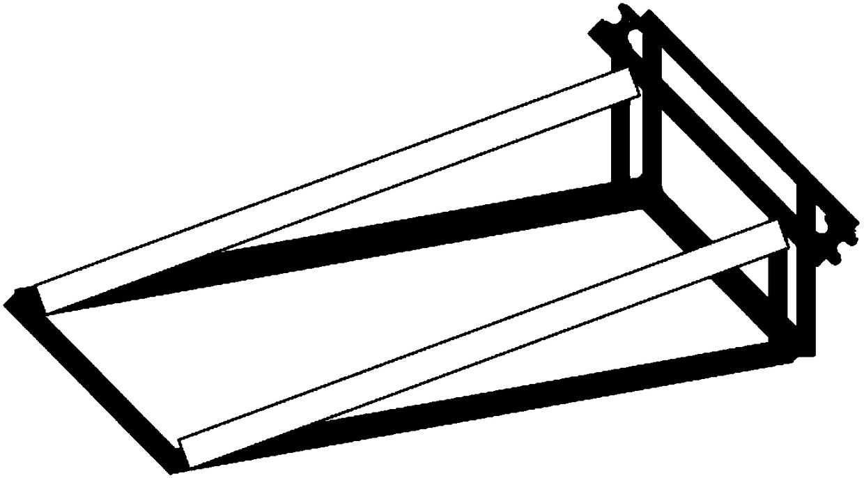
[0029] In the first embodiment, as in figure 1 As shown, a 10kV line ground potential live replacement device for strain rod insulators, including cross-arm brackets and wire tightening devices, in which:

[0030] The cross-arm support includes a rectangular bottom frame, a fixed frame vertically connected to one end of the rectangular bottom frame, the fixed frame is two "π"-shaped brackets, and the top of one "π"-shaped bracket is connected to the other end of the rectangular bottom frame through a connecting plate Connection, a pulley is provided on the upper connection of the two "π" type brackets;

[0031] The wire tightening device includes a wire clamp, a Dyneema rope and a wire tightener; wherein the Dyneema rope is set on the pulley of the cross-arm bracket, and one end of the Dyneema rope is clamped on the wire clamp along the length direction of the wire clamp. On the thread clamp, the other end of the Dyneema rope is wound on the thread tensioner.

[0032] Prefer...

Embodiment 2

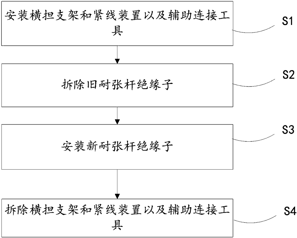
[0037] A method for live replacement of tension rod insulators, the method uses a 10kV line ground potential live replacement device for tension rod insulators, such as figure 2 shown, including the following steps:

[0038] S1: Install the cross-arm bracket and tensioning device and auxiliary connection tools;

[0039] S2: Remove the old tension bar insulators;

[0040] S3: Install new tension bar insulators;

[0041] S4: Remove the cross-arm bracket, wire tightening device and auxiliary connection tools;

[0042] In addition, it also includes routine steps before dismantling and installation, such as: installing on-site safety facilities; checking and testing whether tools and materials are complete; operators arriving at live working stations;

[0043] Conventional steps after dismantling and installation in the past: For example, the operator exits the live work station; cleans up the site, counts tools; and summarizes the work.

[0044] Preferably, in step S1, the cr...


PUM


Abstract

The invention relates to a device and method for lively replacing the tensile rod insulators of a 10kV line by using a ground potential working method. According to the device and method of the invention, the ground potential working method is used to replace the tensile rod insulator string of the 10kV line; by means of the excellent electrical performance of an insulated operating rod and the excellent mechanical and electrical performance of a Dyneema rope, an operator performs operation with the insulating rod ground potential working method, a ground worker uses a line tightening device to tighten a wire; and therefore, an operation process can be simplified, the heavy manual labor burden of the on-rod operator can be decreased, and work efficiency can be greatly improved.

Description

technical field [0001] The invention relates to a device and a method for replacing tension rod insulators with electricity on the ground potential of a 10kV line. Background technique [0002] During the operation of 10kV line tension rod insulators, due to aging, lightning strikes, pollution, external force damage and other reasons, there will be different degrees of deterioration. When it develops to a certain extent, the electrical performance of the insulators will be completely lost, and single-phase or phase-to-phase short circuits will occur. Cause the line to trip and interrupt the normal power supply to the user. Replacing bad insulators in time can effectively improve the insulation level of the line. At present, when carrying out live replacement of tension rod insulator strings on 10kV lines in the company's system, the main method is to use insulating gloves. Some areas cannot be reached by insulated bucket trucks, and the use of insulating maintenance frames ...

Claims


Application Information

Patent Timeline
IPC IPC(8): H02G1/02
CPCH02G1/02
Inventor 王聪智
Owner HONGHE POWER SUPPLY BUREAU OF YUNNAN POWER GRID
Why Eureka
Try Eureka