Workbench for hardware mechanical pipeline clamping

A workbench and mechanical technology, which is applied in the field of workbenches for hardware and mechanical pipe clamping, can solve the problems of increasing waste, achieve the effects of quick and convenient use, simple and reasonable structure, and improve adaptability

Inactive Publication Date: 2018-07-06
COMMON TECH DEV CO LTD
View PDF10 Cites 46 Cited by
  • Summary
  • Abstract
  • Description
  • Claims
  • Application Information

AI Technical Summary

Problems solved by technology

[0003] The use of hardware machinery is inseparable from the processing and use of hardware products, such as grinding, polishing, cutting, drilling and other technical operations. During the use of these machines, some metal pipes or plastic pipes are often processed. The processing of pipes is different from the processing of plates. It is difficult to accurately position and fix the pipes with traditional machinery. Therefore, separate hardware machinery is often designed for pipe processing, but each machine often uses different working platforms. This will undoubtedly greatly increase the voluntary waste, and for the processing of pipes, the main purpose of using machinery is to facilitate the clamping of pipes. Therefore, a workbench for hardware and mechanical pipe clamping with wider applicability is designed. necessary

Method used


Image

  • Workbench for hardware mechanical pipeline clamping
  • Workbench for hardware mechanical pipeline clamping
  • Workbench for hardware mechanical pipeline clamping

Examples


Embodiment Construction

[0021] The technical solution of this patent will be further described in detail below in conjunction with specific embodiments.

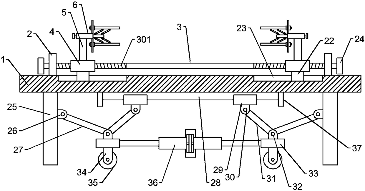
[0022] see Figure 1-4 , a metal mechanical pipe clamping workbench, including a platform plate 1, two support blocks 2 are symmetrically installed on the upper end of the platform plate 1, the support blocks 2 are arranged along the length direction of the platform plate 1, and the two support blocks 2 A rotating shaft 3 is installed between them, and the two ends of the rotating shaft 3 are provided with threaded parts 301. The threaded parts 301 at both ends of the rotating shaft 3 are symmetrical along the center of the rotating shaft 3, and the threads on the threaded parts 301 at both ends of the rotating shaft 3 are opposite. There is a screw sleeve 4, the upper end of the screw sleeve 4 is equipped with a support column 5, and the upper ends of the two support columns 5 are equipped with a clamp 6, and the clamps 6 on both sides are arrange...


PUM


Abstract

The invention discloses a workbench for hardware mechanical pipeline clamping. The workbench comprises a platform board, a supporting block, a rotary shaft, thread portions, barrels, supporting columns and clamps, wherein each clamp comprises a fixing sleeve, a first insertion rod, a first threaded hole, a first lead screw, a first slide block, a first slide groove, a vertical board, a slide holeand a supporting rod; two check blocks are installed on the supporting rods; a first hinge base is installed on the side wall, facing the corresponding first insertion rod, of each supporting rod; a second hinge base is installed on the side wall of one end, outside the corresponding fixing sleeve, of each first insertion rod; and the first hinge bases and the second hinge bases are connected through first connection rods. The barrels and the clamps which are installed on the threaded portions can achieve clamping of pipelines of different lengths, the pipelines of different diameters can be supported tightly through the supporting rods through the structural design of the clamps, the adaption performance of the workbench is improved, idler wheels are designed at the bottom of the workbench, the height of the idler wheel mechanism can be adjusted through a telescopic rod, and the workbench is conveniently moved and positioned.

Description

technical field [0001] The invention relates to a workbench, in particular to a workbench for hardware machinery pipe clamping. Background technique [0002] Hardware: traditional hardware products, also known as "hardware". Refers to the five metals of gold, silver, copper, iron, and tin. After manual processing, it can be made into works of art or metal devices such as knives and swords. Hardware in modern society is more extensive, such as hardware tools, hardware parts, daily hardware, construction hardware and security supplies. Most hardware products are not final consumer goods. [0003] The use of hardware machinery is inseparable from the processing and use of hardware products, such as grinding, polishing, cutting, drilling and other technical operations. During the use of these machines, some metal pipes or plastic pipes are often processed. The processing of pipes is different from the processing of plates. It is difficult to accurately position and fix the p...

Claims


Application Information

Patent Timeline
Patent Type & Authority Applications(China)
IPC IPC(8): B25B11/00B25H1/08
CPCB25B11/00B25H1/08
Inventor 周秋伟
Owner COMMON TECH DEV CO LTD
Why Eureka
Try Eureka