Convenience type foam cutting device

A cutting device and a portable technology, applied in the field of portable foam cutting devices, can solve the problems of high cost of use, low processing efficiency, inconvenient processing, etc., and achieve the effects of low cost of use, high processing efficiency and improved applicability

Active Publication Date: 2018-07-06
贵州大东风机械有限公司
View PDF9 Cites 5 Cited by
  • Summary
  • Abstract
  • Description
  • Claims
  • Application Information

AI Technical Summary

Problems solved by technology

[0002] Foam patterns are widely used. Foam patterns can be cut into foam patterns of different sizes for processing to form ceramic filters. Foam patterns can also be used in the packaging field. At present, the existing foam cutting equipment on the market mainly includes laser cutting, electric heating Wire cutting, etc. Most of these devices have complex structures, high cost of use, inconvenient processing operations, difficult replacement of heating wires, low processing efficiency, inconvenient processing to form a variety of foam patterns of different specifications, and cannot make full use of the heat of foam and heating wires Inadequate use and other issues

Method used


Image

  • Convenience type foam cutting device
  • Convenience type foam cutting device
  • Convenience type foam cutting device

Examples


Embodiment

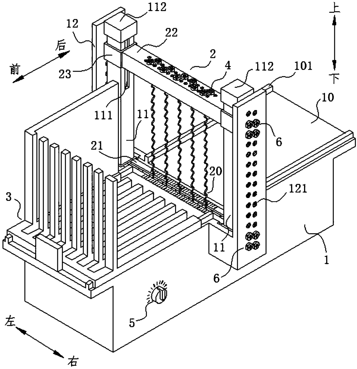
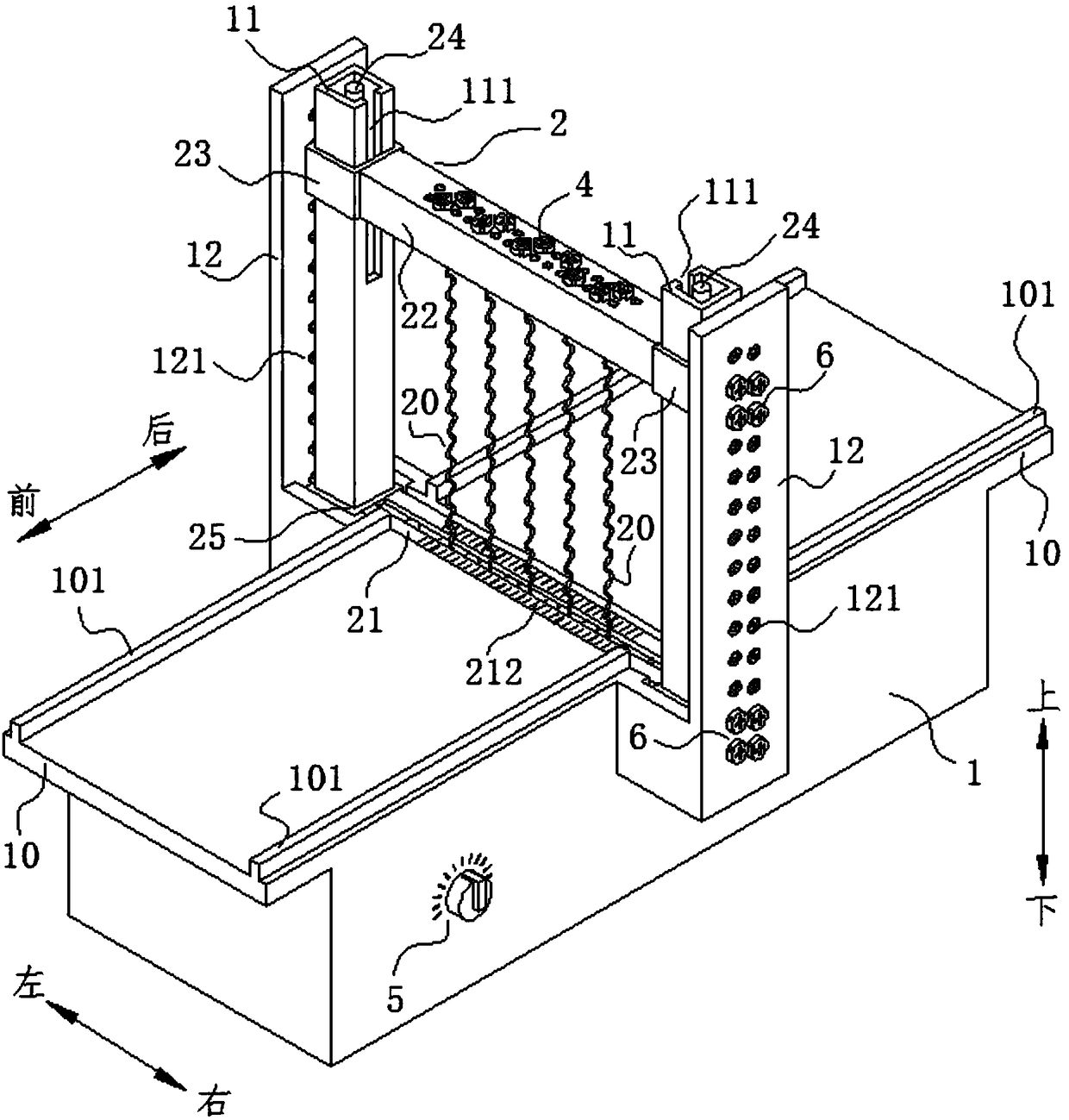
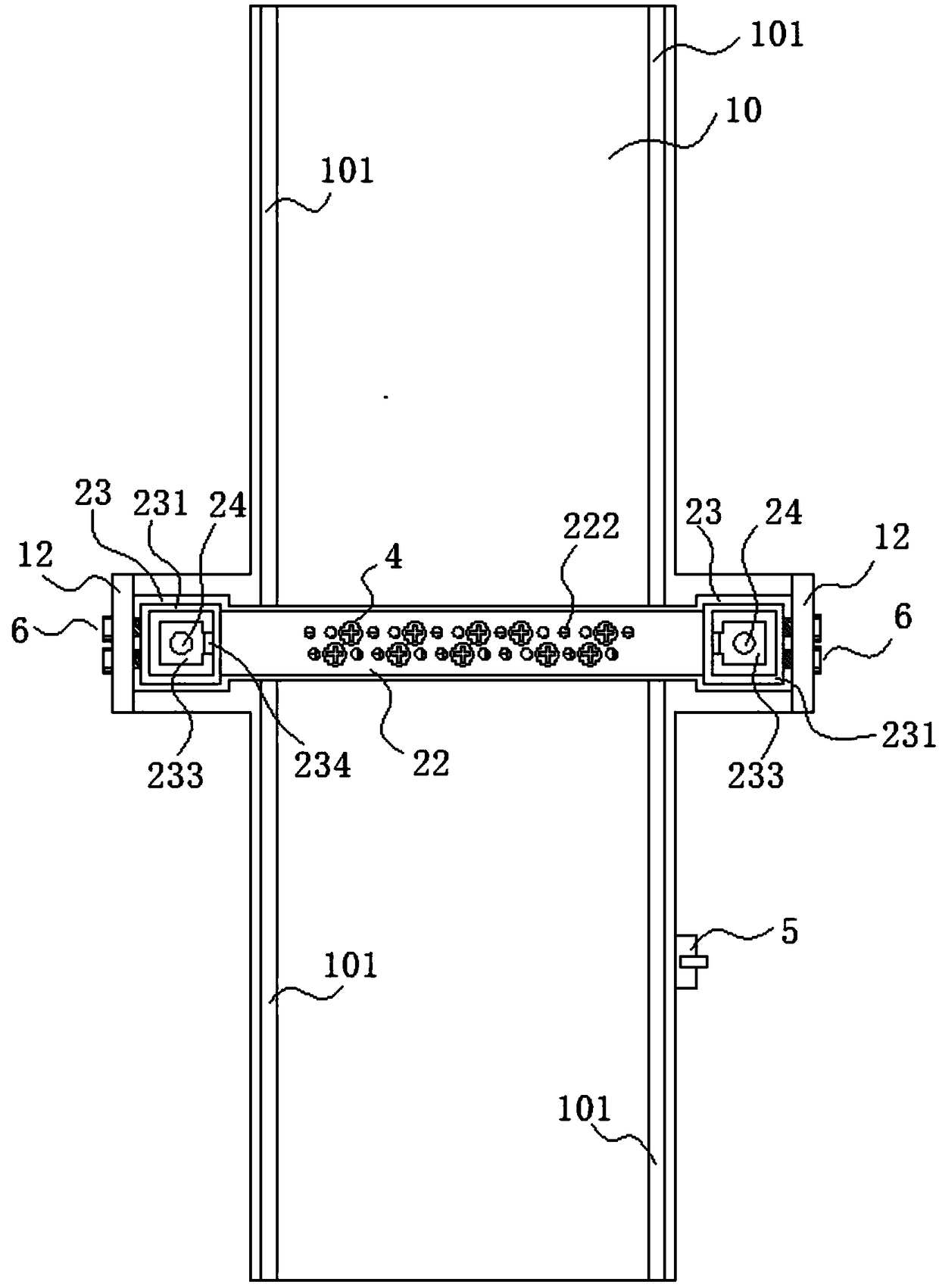
[0033] This embodiment provides a portable foam cutting device, such as Figure 1 to Figure 7 As shown, it includes a base 1 provided with a workbench 10, vertical conductive rods 24 that are vertically arranged on both sides of the base 1 and extend upward, and vertical conductive rods 24 that are respectively covered on the peripheral sides of the vertical conductive rods 24. Guide sleeve 11, a plurality of heating wires 20, and an upper conductive rod 27 and a lower conductive rod 26 for supplying power to a plurality of the heating wires 20 and respectively connected to two poles of the power supply; the two ends of the lower conductive rod 26 can be respectively The sliding sleeve 25 is disassembled and fixedly connected, and the upper side of the workbench 10 is provided with a storage groove 13 for accommodating the lower conductive rod 26 and the sliding sleeve 25, and the sliding sleeve 25 is slidingly sleeved on the vertical on the guide sleeve 11 and set in the rece...


PUM


Abstract

The invention discloses a convenience type foam cutting device which comprises a base with a working table, vertical conductive rods, vertical guide sleeves covering the peripheries of the conductiverods, multiple electric heating wires, an upper conductive rod and a lower conductive rod. The upper conductive rod and the lower conductive rod are used for supplying power to the multiple electric heating wires and are connected with two poles of a power supply separately; sliding sleeves are detachably and fixedly connected to two ends of the lower conductive rod; a storage slot for storing thelower conductive rod and the sliding sleeves is formed in the upper side surface of the working table; the sliding sleeves are slidably arranged on the vertical guide sleeves in a sleeving mode and located in the storage slot of the working table; conductive sliding sleeves are detachably and fixedly connected to two ends of the upper conductive rod, are slidably arranged on the vertical guide sleeves in a sleeving mode and are connected with the vertical conductive rods; the sliding sleeves and the conductive sliding sleeves are connected onto the vertical guide sleeves through locking partsin a locking way; and the multiple electric heating wires are connected between the upper conductive rod and the lower conductive rod at intervals. The convenience type foam cutting device has the advantages of simple structure, convenience in processing and forming multiple foam models with different specifications, high processing efficiency and low use cost.

Description

technical field [0001] The invention relates to the technical field of foam cutting equipment, in particular to a portable foam cutting device. Background technique [0002] Foam patterns are widely used. Foam patterns can be cut into foam patterns of different sizes for processing to form ceramic filters. Foam patterns can also be used in the packaging field. At present, the existing foam cutting equipment on the market mainly includes laser cutting, electric heating Wire cutting, etc. Most of these devices have complex structures, high cost of use, inconvenient processing operations, difficult replacement of heating wires, low processing efficiency, inconvenient processing to form a variety of foam patterns of different specifications, and cannot make full use of the heat of foam and heating wires Utilization is not advanced issues. Contents of the invention [0003] The purpose of the present invention is to overcome the shortcomings of the above-mentioned prior art, a...

Claims


Application Information

Patent Timeline
Patent Type & Authority Applications(China)
IPC IPC(8): B26F3/12B26D7/26B26D7/22B26D7/00
CPCB26D7/00B26D7/22B26D7/2628B26F3/12Y02W30/62
Inventor 林文帜黄昌辉何祖圣
Owner 贵州大东风机械有限公司
Why Eureka
Try Eureka