
Environment-friendly cloth drying device

A cloth drying and environmental protection technology, applied in drying, drying machines, heating devices, etc., can solve the problems of low drying efficiency of cloth, environmental pollution, health impact of workers, etc., to improve environmental protection, reduce production costs, The effect of improving safety

Active Publication Date: 2018-07-06
常熟三和兴针纺织品有限公司
View PDF9 Cites 25 Cited by
  • Summary
  • Abstract
  • Description
  • Claims
  • Application Information

AI Technical Summary

Problems solved by technology

The existing dryer mainly includes a drying box and a heating device arranged inside the drying box. The air in the drying box is first heated by the heating device, and the temperature of the air in the drying box is reached by the heating device. After the specifications are required, the heated air is used to dry the cloth. Because the cloth contains a large amount of water or dye solution before drying, the drying efficiency of the cloth is low, and the dye will produce certain harmful gases when heated, which is currently harmful. The gas is directly discharged into the atmosphere, which not only causes some pollution to the environment, but also has a certain impact on the health of workers

Method used


Image

  • Environment-friendly cloth drying device
  • Environment-friendly cloth drying device
  • Environment-friendly cloth drying device

Examples


Embodiment

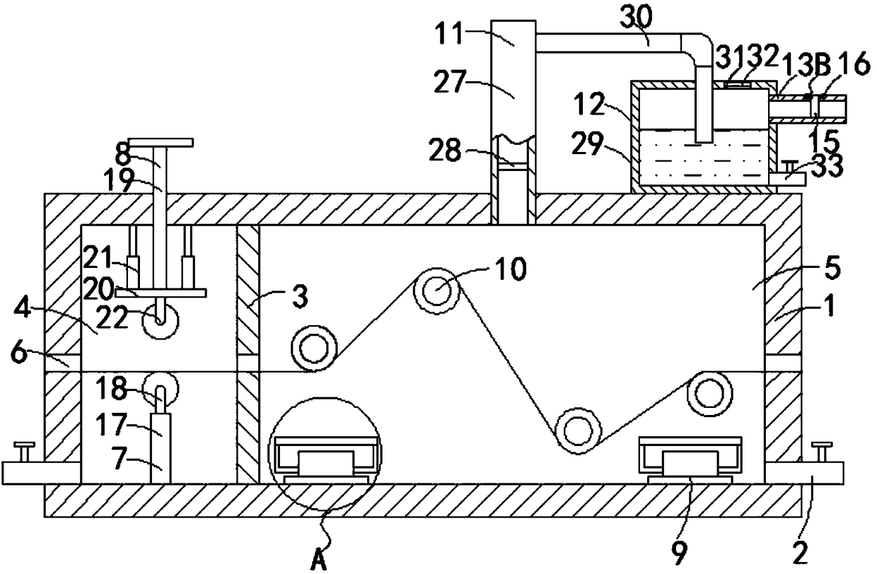
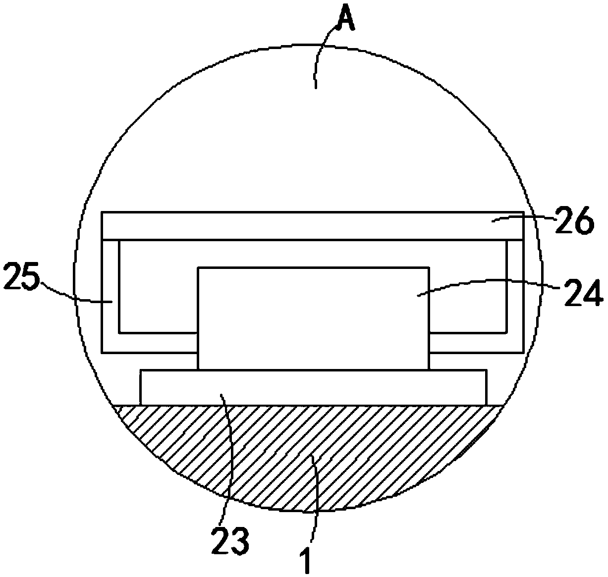
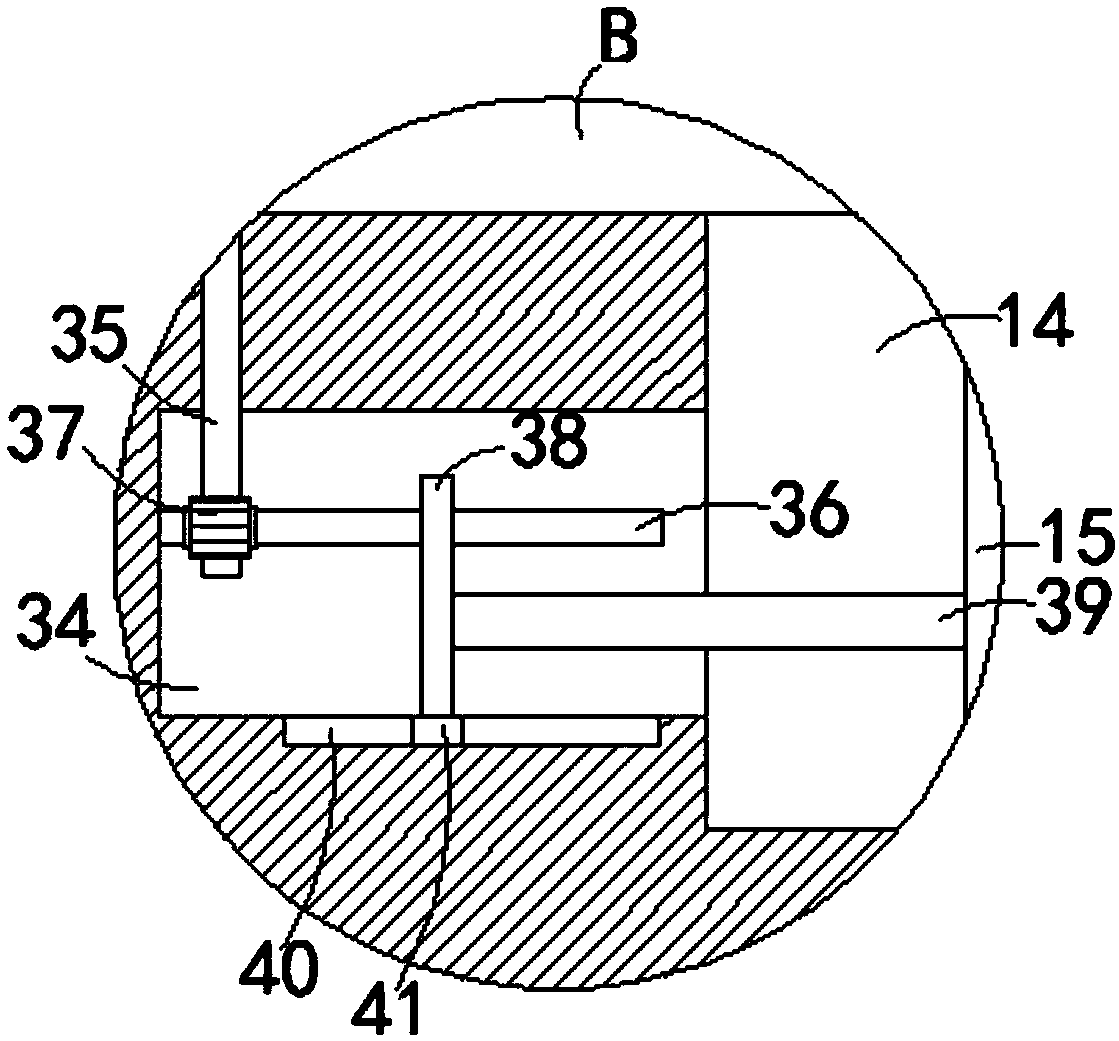
[0021] Such as Figure 1-4 As shown, an environment-friendly cloth drying device includes a drying box 1, a plurality of first drain pipes 2 are connected to the side walls of the left and right ends of the drying box 1, and the first liquid drain pipes 2 are installed with trapping first A flow control valve is convenient to control the discharge of liquid in the drying box 1. The drying box 1 is vertically provided with a partition plate 3, and the upper and lower ends of the partition plate 3 are respectively fixed to the top surface and the bottom of the drying box 1. connected, the partition plate 3 separates the drying box 1 into a dehydration chamber 4 and a drying chamber 5, and the inner walls of the left and right ends of the dehydration chamber 4 and the drying chamber 5 are all provided with cloth openings 6, and the bottom of the dehydration chamber 4 is provided with There is a lower extruding device 7, an upper extruding device 8 is provided on the top surface o...


PUM


Abstract

The invention belongs to the technical field of textile equipment, and particularly relates to an environment-friendly cloth drying device. The device comprises a drying box, a plurality of first liquid discharge pipes are connected to the side walls of the left end and the right end of the drying box, a separation plate is vertically arranged on the drying box, the upper end and the lower end ofthe separation plate are fixedly connected with the top surface and the bottom of the drying box correspondingly, the separation plate divides the drying box into a dehydrating chamber and a drying chamber in a separating mode, the inner walls of the left end and the right end of the dehydrating chamber and the inner walls of the left end and the right end of the drying chamber are provided with cloth through openings, the bottom of the dehydrating chamber is provided with a lower extruding device, the top surface of the dehydrating chamber is provided with an upper extruding device, the upperextruding device is located right above the lower extruding device, a plurality of drying devices are arranged at the bottom of the drying chamber, a plurality of guide rollers are rotationally connected to the inner wall of the rear end of the drying chamber, and a first through hole making the inside and the outside communicate is formed in the top surface of the drying chamber. The device hasthe advantages that the drying efficiency of the cloth can be effectively improved, harmful gas generated by drying the cloth can be absorbed, and the environmental protection property of cloth dryingis effectively improved.

Description

technical field [0001] The invention belongs to the technical field of textile equipment, and in particular relates to an environment-friendly cloth drying device. Background technique [0002] As we all know, the dryer is one of the essential production equipment in textile production, and the quality of the dryer will directly affect the quality of the textile. The existing dryer mainly includes a drying box and a heating device arranged inside the drying box. The air in the drying box is first heated by the heating device, and the temperature of the air in the drying box is reached by the heating device. After the specifications are required, the heated air is used to dry the cloth. Because the cloth contains a large amount of water or dye solution before drying, the drying efficiency of the cloth is low, and the dye will produce certain harmful gases when heated, which is currently harmful. The gas is directly discharged into the atmosphere, which not only causes some p...

Claims


Application Information

Patent Timeline
IPC IPC(8): F26B13/14F26B13/28F26B23/00F26B25/00D06B15/00D06B15/02
CPCD06B15/00D06B15/02F26B13/14F26B13/28F26B23/00F26B25/00F26B25/005
Inventor 张崟
Owner 常熟三和兴针纺织品有限公司
Learn More